
This is another wheel reinvention exercise, as so many other peltier fridge projects are out there. Here’s another one.
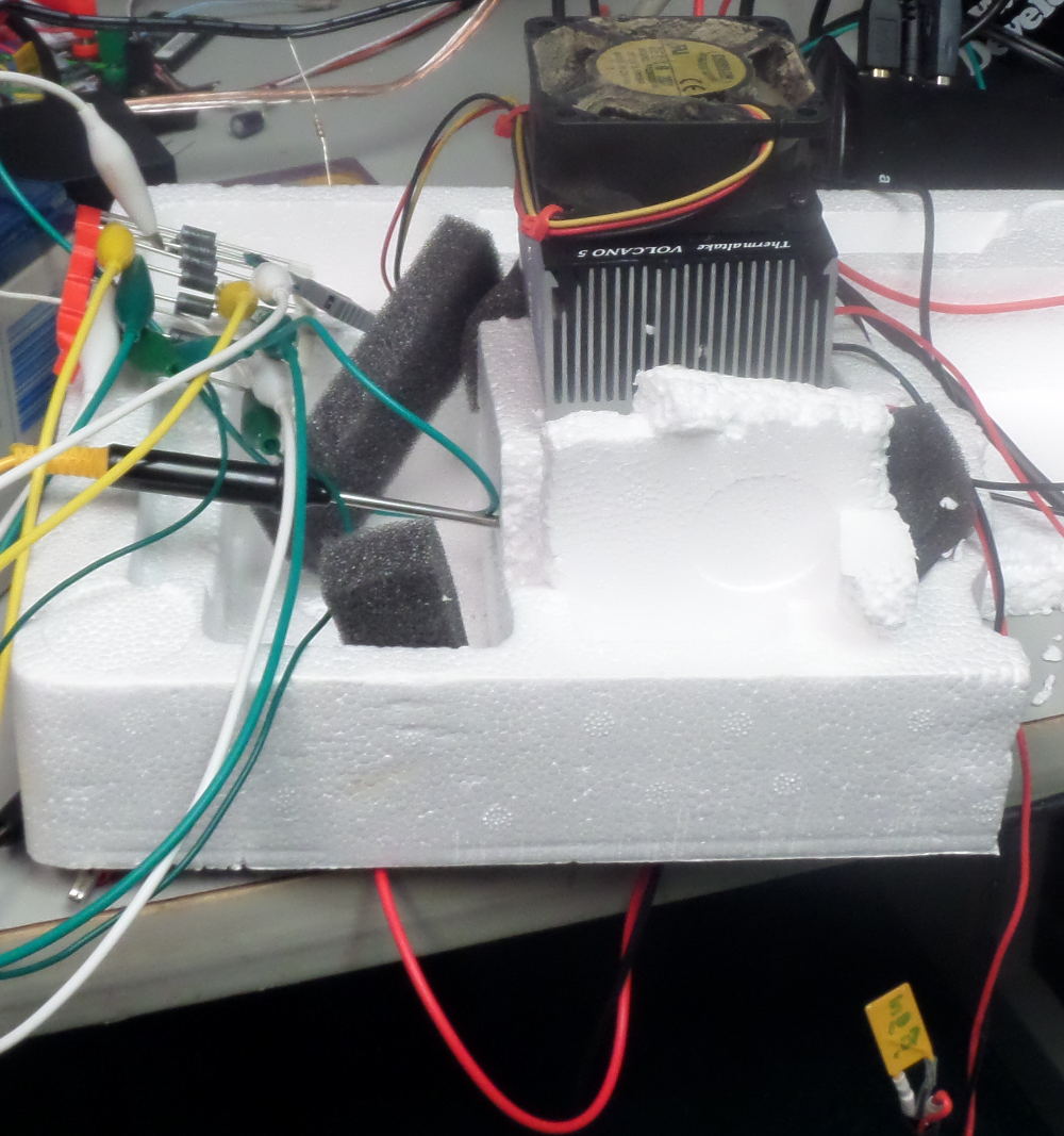
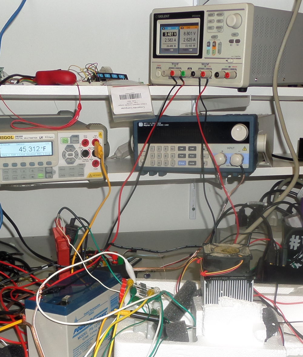
In the picture above two PC CPU heatsinks are the outside of a peltier device sandwich, with an old fan running on top. Approximately nine volts at two and a half amps is fed into one device from the bottom of the picture through a PTC fuse that was already lying around (used with a four-D-cell ‘squishy circuits’ setup). This is driven with a power supply (shown below), with the PS second channel powering a second peltier device along side the first.
The type K thermocouple stuck into the bottom heatsink shows a reasonably chilly temperature (roughly 30 degrees F colder than the room).
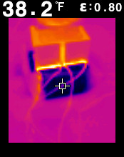
Here’s a thermal image of the bottom side of the prototype showing at least part running at 38F. Note that I haven’t spent a second to figure out whether the imager’s emissivity setting is appropriate for this situation, so the thermocouple’s vote of 45 degrees may reflect reality or reality might be somewhere in between.
But these results make me optimistic that I can build a small fridge for keeping solder paste and methylene chloride (acrylic adhesive) properly chilled. By building the whole thing in a plastic box with a plastic top mating with the “cold” heat sink with a gasket, I think it may also be possible to maintain a very low moisture level inside the fridge which is good for paste shelf life. A relatively simple thermostat should work to keep the fridge at or below 40 degrees F.
One detail that might be of interest in the top photo is that the fan is powered off a battery that happened to be handy but with a charger on it too the fan was racing. It’s 15 years old and I wouldn’t want to rob it of it’s golden years, so I dropped the voltage with a set of jumpers on a cut-tape row of rectifiers to the left of the heatsinks. The zig-zag connection between rectifiers drops the roughly 13 volts from the battery down to 9-10 volts to run the fan at a more leisurely rate. Only a little air movement is actually needed to keep the “hot” heatsink within a small number of degrees of ambient and a low sound level is an added benefit of the lower voltage.
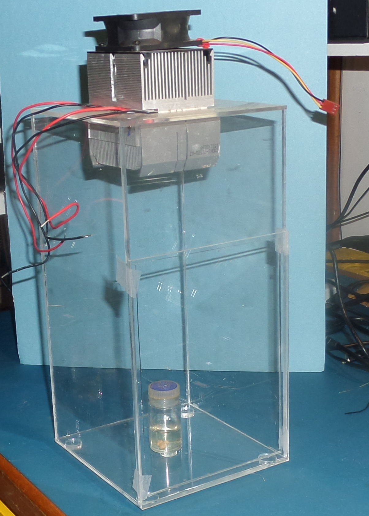
Here’s the fridge with the door held on by tape. Proper hinges are on the way. Some tabs are going around the top so the “lid” with the heatsinks can slot into the space with no danger of tipping into the opening. Some insulation on the top sheet of acrylic around the “cold” heatsink on the underside and other insulation around the top heatsink sitting on the acrylic seems in order.
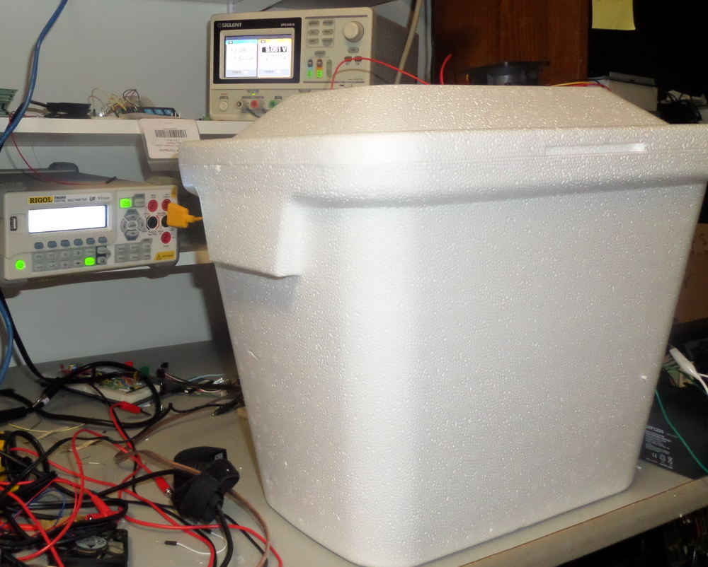
You can just see the cooling fan poking out the top of the styrofoam. No attempt was made to avoid heat getting inside the styrofoam: this is just a quick test. But the thermocouple poking inside the fridge in the cooler does not need its wooly underwear, and it’s getting warmer, not cooler. This configuration appears to need work!
One peltier device had failed open, so it was just moving heat from the upper heatsink to the lower. Subsequently a second peltier device failed open. They have not been run out of spec and the heatsinks have kept their temp differences and max temps well within spec. I’m disappointed. Various tests with one and two devices using much better insulation have been dismal in terms of the amount of energy that appears to be needed to match a cheap “dorm fridge”. I’m going to retrieve my daughter’s fridge from storage and measure its power consumption once it gets a double sealed pot of solder paste and triple sealed can of acrylic cement down in the mid 30s F and then decide whether to put any more time into this project.