Project Links: Home, Sensor, Design, Cost, Software, Web
When I discovered that the sensor I wanted to use a surface mount device, I knew that making the custom board to support it would have the longest lead times. So, I started here with only a couple boundary conditions – it would need to work on 3.3 or 5V and I only wanted a 6 conductor cable so it would need to communicate with I2C. Here are the major elements and their function:
- Gas Sensor – I found a distributor for SGX Sensortech Limited who carries a complete line of Metal Oxide Gas Sensors. There is a family that all share a common footprint so you can select the sensor you want to use. Here is dual CO and NO2 sensor that I will start with.
- MICS Quick Start Board – This is where I started butI decided that I could design a much more functional board for less than what they were charging.
- Temperature and Humidity Sensor – I chose the Honeywell, HIH6130 as it was compact, i2c and 3.3 and 5V tolerant.
- I wanted to control the board with only 6 wires, two for a 3.3 reference, two for i2c and two for control – on/off and preheat/fan. To do this, I added a Fairchild inverter which would alternately pre-heat the sensor or turn on the fan via a pair of NXP N-MOSFETs.
- Digital to Analog Converter – I have to admit, I have a bit of a digital bias. By converting the Gas Sensor’s readings from analog to digital, I could use less wires and run the sensor board at 5V while my main board runs at 3.3V or 5V. I used a TI four channel Digital to Analog Converter with two channels for the Gas Sensor, one to measure the battery voltage and one routed to a header for future use.
- i2c Level Converter – Using this converter, you should be able to use this board with either 3.3V or 5V i2c as the logic level for the output header is set by the two wires you feed from your controller. Have not done this before, but it seems straightforward. I used the TI Bi-Directional i2c device.
- Power Supply – This was one of the areas that drive me to design my own board in the first place. The quick start board used a simple linear supply but I like the switched TI TPS63002 as it allows for a wide range of battery voltages and takes only a few components. One nit, the PowerPad chip is hard to solder and I had to create a custom footprint as the ones TI gives you are junk.
Here is the schematic for this board:Air Quality Board
I have placed the EAGLE files in the Air Quality Sensor Project Github Repository. Please note, this board is currently untested.
This is the current layout – about 1″ x 2.25″ – need to add more labeling but you can see how it all fits: 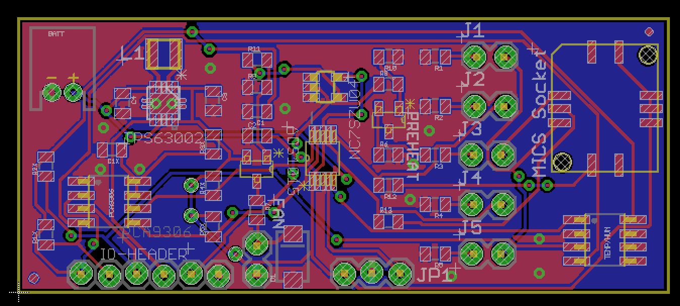
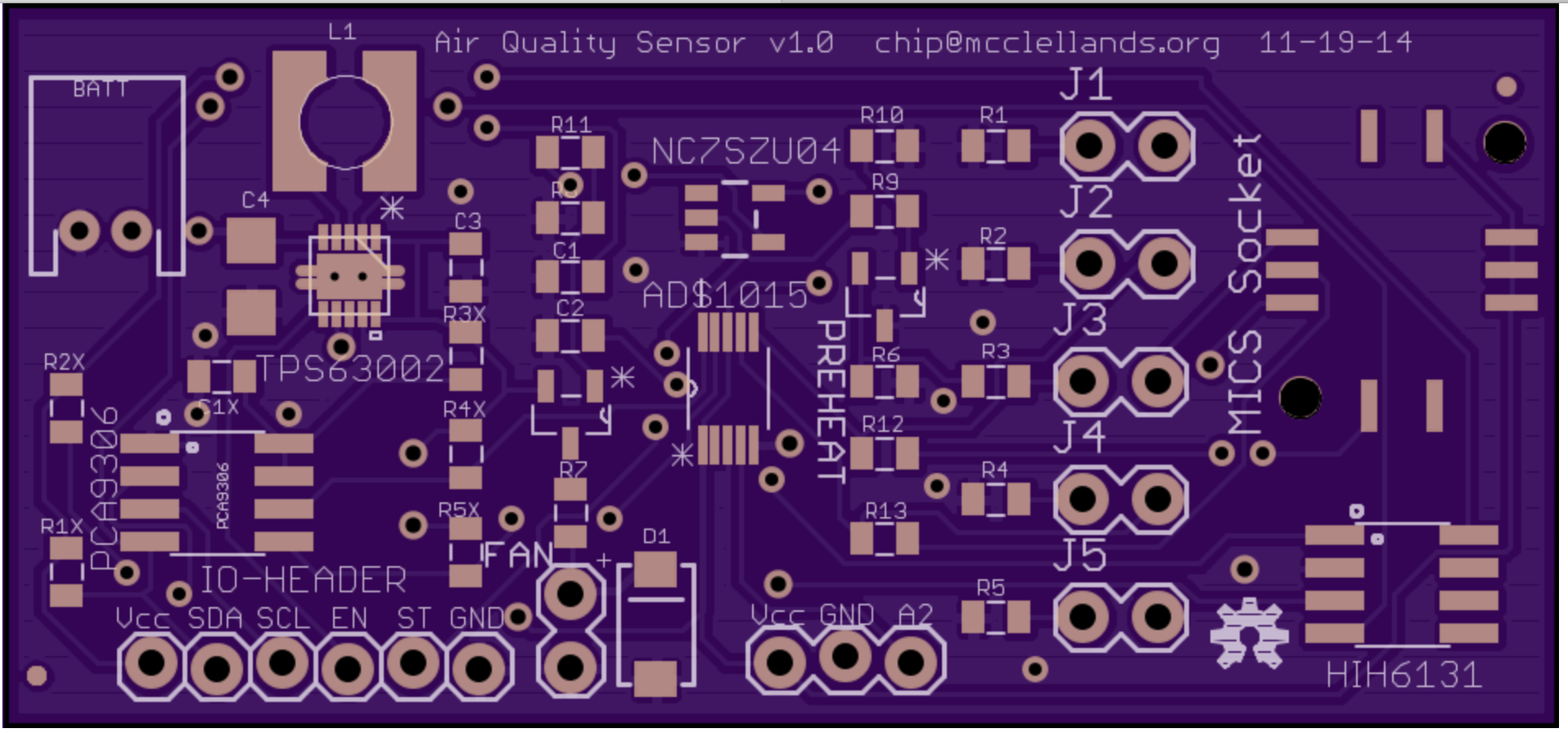
Update: Finalized the board and sent to OshPark for production. Here is what the board will look like:

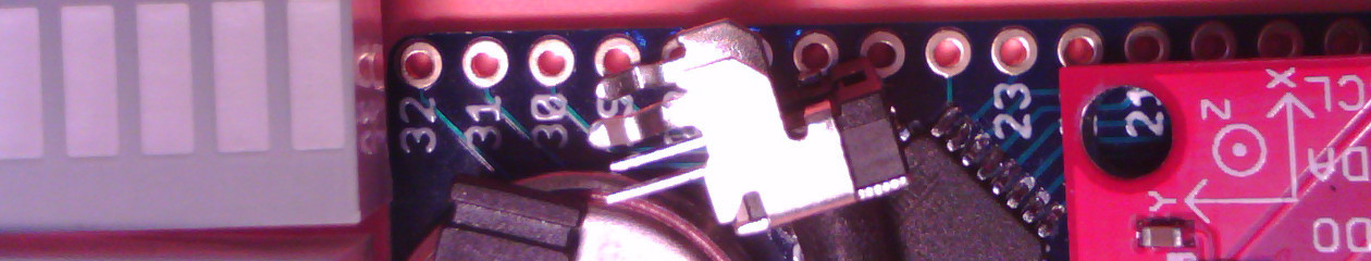
The board is making its way to me from Portland and the USPS is taking their sweet time in delivering it. Someday when I have more money, I will pay for UPS or FedEx delivery….
FYI. Your link to the first sensor says it detects “CO and NO2”, but i noticed on the linked site that it says it detects “carbon dioxide and nitrogen dioxide”.
Hmm.. this appears to be an error on the cdiweb site. Another place on the page it says carbon monoxide! Disregard.. 🙂