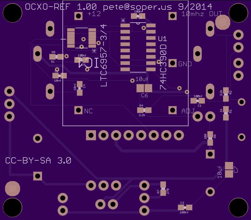
Here’s the first version of the oscillator/power supply regulator portion of the callibrator/frequency counter project. This part of my calibrator/counter project was done in September/October of 2014. I just got back to updating this blurb. This circuit works fine: no bugs found so far. But I have a rubidium standard and HP5335A counter these days and can use these bits along with my oscilloscope to get this OCXO to perform as well as it’s capable of performing.
Several component choices were determined by what’s filling my parts drawers vs “best”. This board will plug in as a daughter board for the rest of the calibrator with 6-32 standoffs to hold it in place.
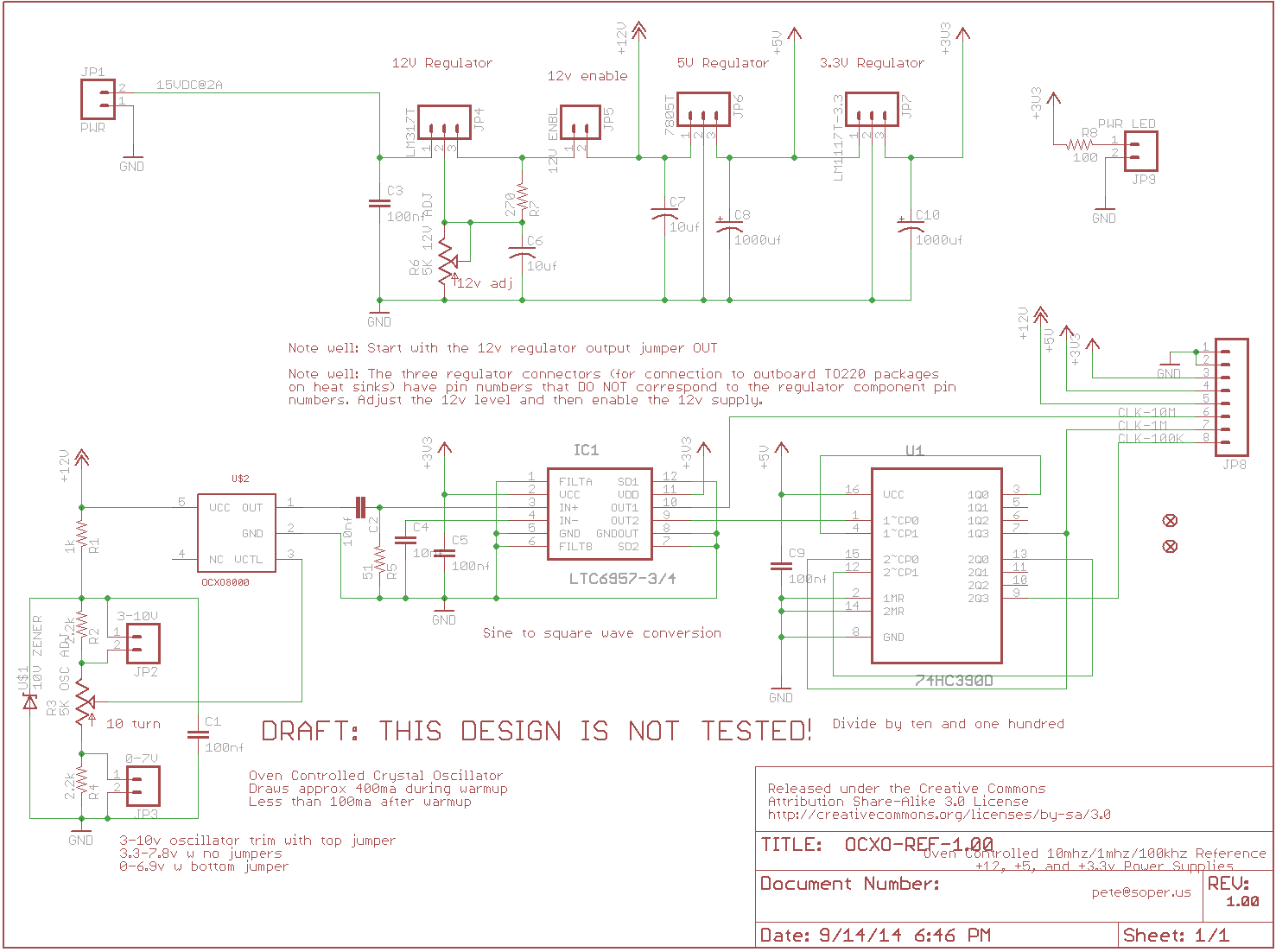
The input is DC of at least 15 volts to give the LM317 margin to reliably put out 12 volts. A Toshiba laptop adaptor I have puts out up to four amps at 15 volts, so that should take care of that! The three voltage regulators will be on substantial heat sinks so they should actually be good for their full rated current.
The output is 12, 5 and 3.3 volts DC and 10, 1 and .1mhz reference square waves. The 10mhz clock comes straight out of one of the Linear Tech sine/square converter chip’s outputs while the slower speed clocks come out of the 74HC390 decade dividers.
The jumper in the 12v path is to allow getting this supply set properly before powering up the OCXO for the first time. The two other jumpers are for enabling the full range of frequency trim control voltages. It appears that during my lifetime something close to five volts will put this oscillator within a few ppb of 10mhz, but in case something with this or some similar oscillator down the road needs a much different voltage I wanted it covered. This scheme translates to a fair fraction of one turn for a hundredth of a volt, making the adjustment much less touchy than the breadboard circuit is.
The point of the lower frequency outputs is to allow prototype/debug of parts of this system on a solderless breadboard. I’m convinced it would be hopeless to do this at 10mhz with all the capacitance across a large breadboard, so one of the lower speeds will be used with longer sample periods and software compensation. Then when everything is in PCB form that should be stable at full speed the higher speed reference will be used.
Something I haven’t done yet is to estimate how much temperature changes will affect the oscillator trim voltage. A “blanket” to thermally couple the relevant resistors and the zener with the OCXO to keep the temp more stable might be useful.
The specific OCXO used is a Raltron OX6589A-LX-10-10.000-12 sold by “happy-man” on Ebay for two or three dozen bucks. Mr Happy-man sends a data sheet with these units showing the actual performance with trim voltages using an HP-5386A and Rubidium reference. I’m very, very happy with Happy-man!
Thanks to Gene Kahn for help with design and debug and for the use of his fantastic test equipment.
The board design is actually at 1.01 already (but 1.00 is in the pipes at OSH Park).
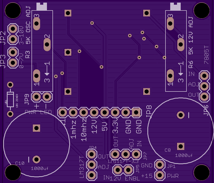
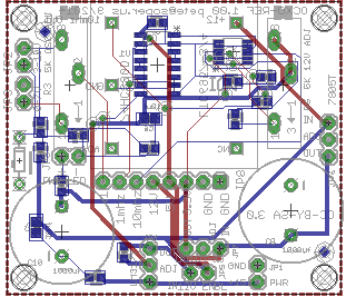
Speaking of, this is another case where I found it much easier to put the surface mount parts on the bottom so the top is left with enough room for legends. I need all the help I can get with wiring things properly and although the SMD parts would easily fit under the OCXO on the top surface of the board (after switching the ‘390 counter chip to TSSOP) it would have made for some pain and suffering that is avoidable. But the mounted board will look a lot simpler than it is. Three copies of this board from OSH Park are costing $17.50. If I could stand the extra time I’d definitely try out DirtyPCBs to see what their boards are like, but this board is on the critical path for the rest of the system.
I never got around to trying the alternative PCB vendor above. OSH Park has been a mouse-operated PCB machine, delivering flawless product. I’ve only played with three other sources out of curiosity but have no intention of switching away from OSH Park for small prototype boards. Also, if you want to fly first class, get a stainless steel stencil for the SMD parts from OSH Stencils. Now days I would hand solder these relatively large parts and not bother with a stencil or oven (or hot air), but it’s harder to get pro quality appearance with hand soldering (especially since I cut over to lead free for all hand soldering for the sake of any kids visiting).
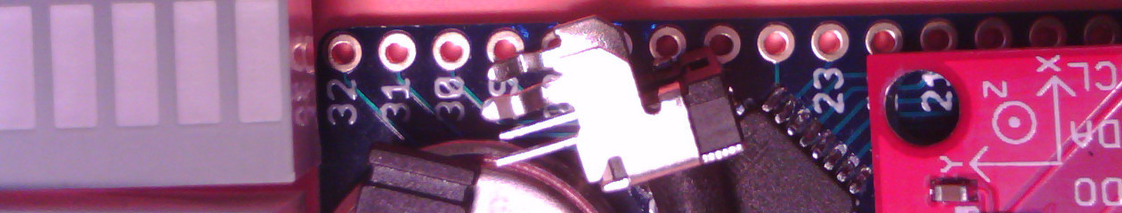
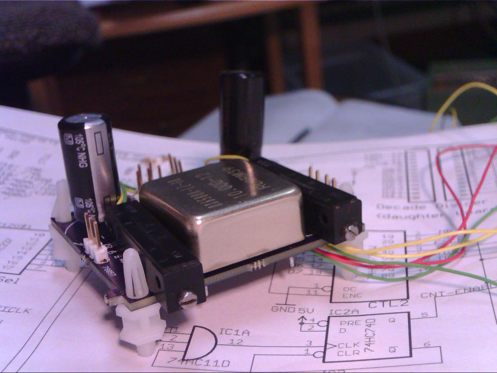
There was a very confusing remark above implying the silkscreen for the OCXO component was wrong. I can’t see any differences between 1.01 and 1.00 wrt to this and can only assume I fixed this and didn’t fix the remarks. I deleted it. The parts go in just as shown in the photos, and I just double checked the board: no cuts or ECO wires needed. One thing, though: looking at this board about three years later provided another vote for thorough removal of flux. I think I was using “God Knows What” brand solder back and obviously didn’t get the board cleaned properly: one of the Linear Tech pins is visibly corroded!! Shocking. These days I use NC solder, but when in doubt I clean with MG flux remover.
Finally, those electrolytic caps are stupidly large. Smaller values can be used (but always bypass on the “other end” if feeding something power more than a few inches away.)
UPDATE 7/2017: The rev 1.01 Eagle schematic and board files and PDFs are available in this zip file. There were no functional changes between 1.00 and 1.01: just silkscreen changes. The board can be ordered from OSH Park from this link.
I would like to make the oscillator board. Do you have a zip file or .brd or do you sell them?
Thanks for the interest. I updated the bottom of the project notes and added a link to Eagle and PDF files. Note also that the trimpots I used did not have through-hole solder connections: they are glued to the board, with wire leads connected to the bottom of the board, so double check and tweak those footprints as needed for your trimpots. Many other changes seem pretty obvious these days, but as you could see, I had to move on and the other part of the project is still occupying a large set of breadboards, waiting for some love. This was a learning project, and one thing I learned is that even “slow” logic doesn’t play well at all on a solderless breadboard! Being over the urge to get my hands dirty with 74HC logic, if I was going to do this project again I’d “throw software at it”, leveraging the hardware counters in a microcontroller with this OCXO circuit still used for accurate timing. This would make it so easy it might not get parked unfinished for multiple years. 🙂
Best Wishes,
Pete
The board is now available from OSH Park via the link near the end of the notes above.