Here are some PCBs I’ve made with OSH Park and OSH Stencils. Most are simple breakout boards aimed at making it easy to test and characterize a particular chip I’m interested in applying.
These images are the renderings the OSH Park “robot” makes from board design file(s) and a few pictures of what the finished circuits look like. In some cases the outline is truncated so top and bottom look different sizes, and there’s no sense of scale: the 1/10 inch header pads are the one good size reference. The detail of the fine pitch component pads is simply nonexistent, unfortunately. There’s one example below of the greater detail you can get from your CAD tool.
You might wonder why these aren’t in the OSH Park “Shared” collection? It’s because decades of work for very picky employers doing software work like revisions of Java at Sun Microsystems make it very difficult for me to release buggy designs, and if I haven’t tested something it’s doubly hard to imagine that it will “just work”. In the real world this stuff doesn’t often “just work” unless you’re doing something for the Nth time where N is at least two.
For instance, had I put the first version of the 2-axis mag board described below into the OSH Park shared area any number of people might have tried to solder that board, but it had a design problem with the component pad area that would have made that torture. When I’m satisfied with a board design and think others might be able to use it I’ll share it. The Freescale mag/accel board shown next will go out right after I fix a pad length problem. In theory I can test this version and then just shorten the pads and share that without retests. My skin is starting to itch now..
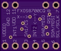
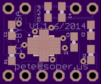
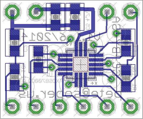
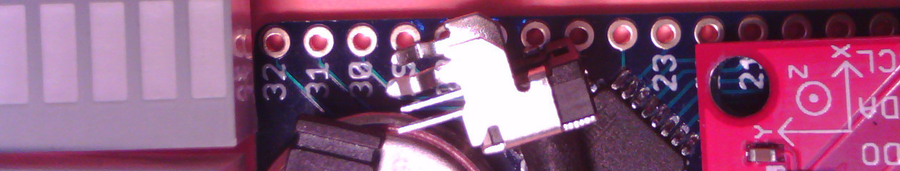
The next to the final version of a Freescale 3-axis magnetometer/3-axis accelerometer board. The components are on the bottom side so a useful legend can fit on top. This makes the North/East orientations with respect to each other different than they’d be if the chip was on the top (i.e. you have to add at least one minus sign to your driver if it was written for the more common case). The pads for the FX are extra long ’cause Chip McClelland and I convinced ourselves this was a good thing while we learned how to solder fine pitch QFN chips. We were mistaken! Not only do these long traces fail to make it any more likely a person could solder this chip with an iron (it has *no* pad on the side of the package: fergetaboutit!), but it makes bridges more likely (thankfully they happen away from the underside of the chip). Notice the dark square on the top of the board. That’s where the copper is suppressed that would be on the other side of the board from the mag sensors. The mag sensor vendors recommend no copper under the sensors (most especially plain traces or vias) so there is no current flow that might make a magnetic field that competes with the Earth.
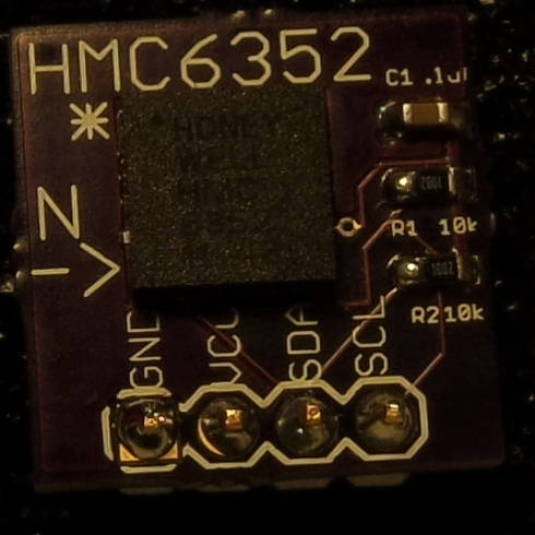
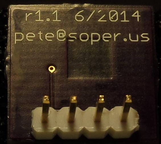
Honewell HMC6352 2-axis magnetometer breakout. This is a scratch implementation of the Honeywell reference circuit, but has the same dimensions as the Sparkfun breakout and looks very similar. If you’re so desparate and ill-informed or stuck between a rock and a hard place such that you’re forced to use this magnetometr chip you can source the chip from Arrow and duplicate the Sparkfun board for roughly a third the cost, so then the solution is only three times as expensive as a 3-axis plus tilt-compensated solution using a modern chip like the Freescale part above. So I’m not going to push this to OSH Park as a public service. (If you really, really need this design I’ll mail you the Eagle files but you must promise not to let them escape into the wild).
Important design note: Non-pad copper and solder mask is suppressed across the entire area where the chip sits. This was a critical fix: an earlier version had amazing “shelves” at the corners that made it virtually impossible to solder the mag chip.
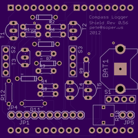
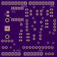
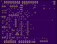
This is a early version of the “Pathfinder I” logging compass. Not interesting.
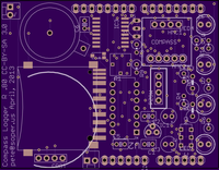
This is the completed “Pathfinder I” logging compass based on an HMC6352, a DS3231 clock/calendar, and a custom SD card interface. It connects to an Arduino Uno as a shield. There is support for the clock as a raw SOIC on the bottom with backup battery on top or in an Adafruit Chronodot that mounts over the top of the SD card socket.
Here are some problems:
- It requires a few trace cuts and ECO wires to fix bugs (2-3 cuts and four wires, as I recall)
- The system this board is part of consumes too much power and is grossly oversized. At very least it needs an Atmega328p board that doesn’t have USB chips on it that are constantly sucking juice.
- The HMC5362 is obsolete and overpriced and can’t walk and chew gum at the same time: sharing this board design might encourage people to use it.
- A newer chip with tilt compensation is a now brainer. However, it should be relatively straight forward to retrofit a decent chip onto this board using the existing connection sites.
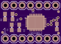

This is an ST LSM330DLC accelerometer/gyroscope board. In theory this chip would allow implementation of a simple inertial guidance system.
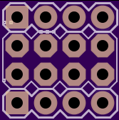
This is an adapter to allow plugging the ubiquitous Nordic Semi NRF24L01+ radio board with it’s eight pin header into a breadboard via a simple .3″ DIP header. I have a large number of these in case anybody needs them. The use of the square pads was, uh, a brain fart on my part. There should only be one, on the top side of the board to provide a clue about where ground ought to be as a reference. But I’ve made a cute stick on label that goes around the radio board female header to make the pin connections obvious.
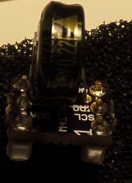
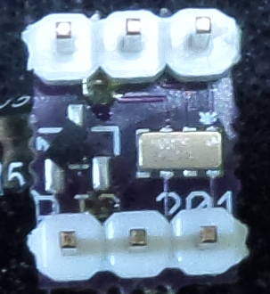
This is a very small breakout for an ST M41T62LC6F clock/calendar chip with supercap backup. The only other component is a schottkey diode (a temporary alternative to the SOT23 version spec’d). It seems to be working and I just need to characterize the supercap performance with and without the squarewave output enabled. This is a relatively small (.22F) cap just intended to make it easy to change the batteries of a system while avoiding a separate lithium battery for the clock.
OCXO-REF-0100
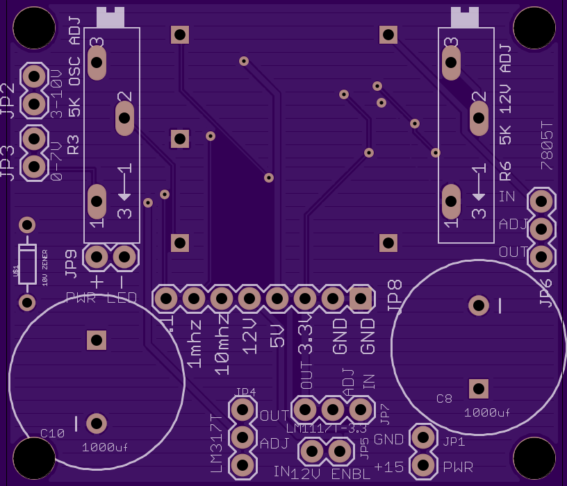
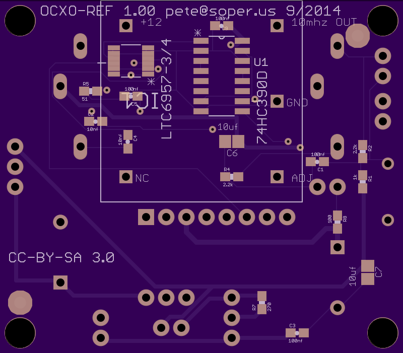
The two images above are the OSH Park renderings of a precision 10mhz (and 1 and .1mhz) reference based on an OCXO and zener trim reference. The surface mount components are on the bottom while through hole are mostly on the top.
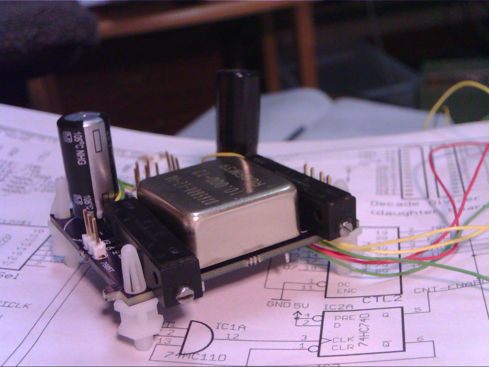
OCXO-DIV-0100
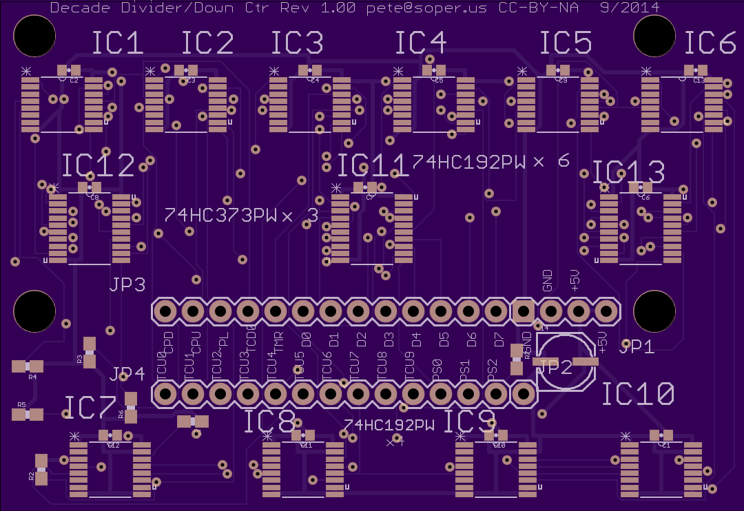
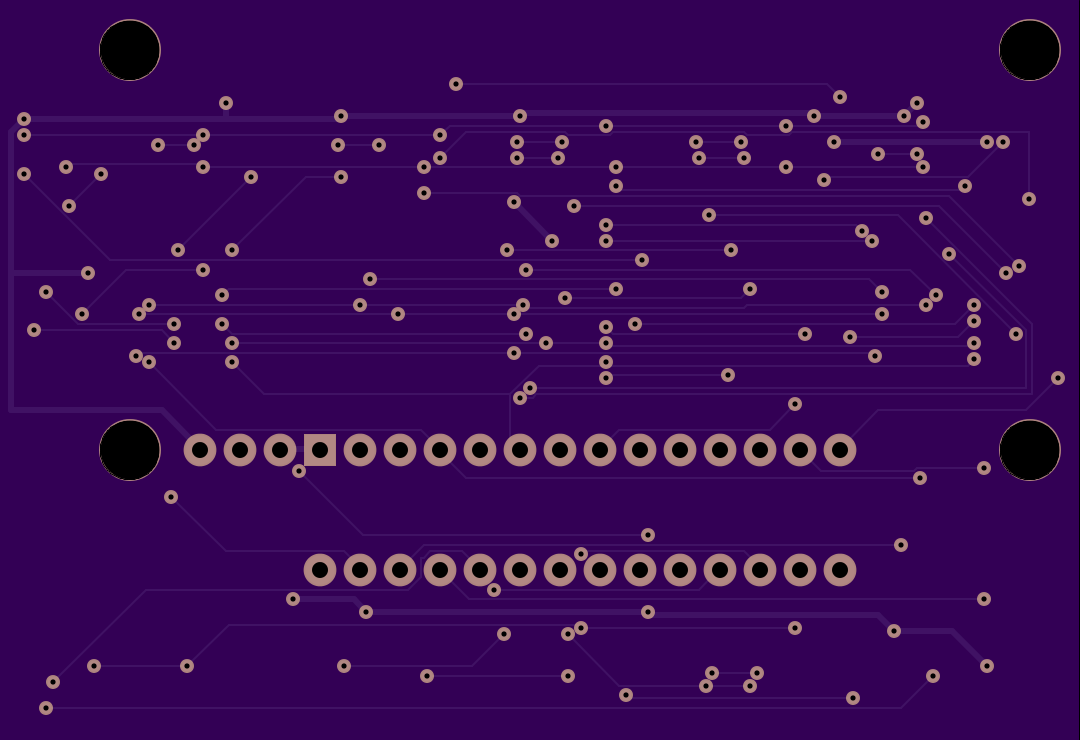
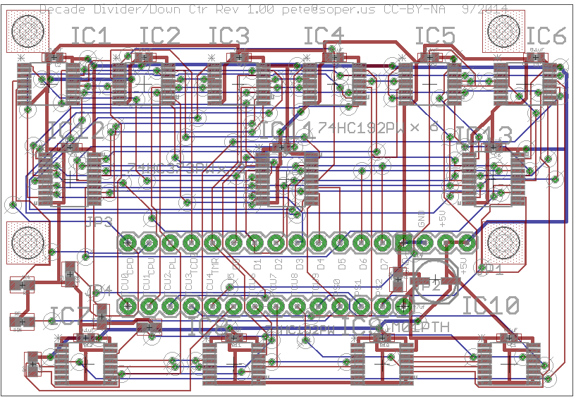
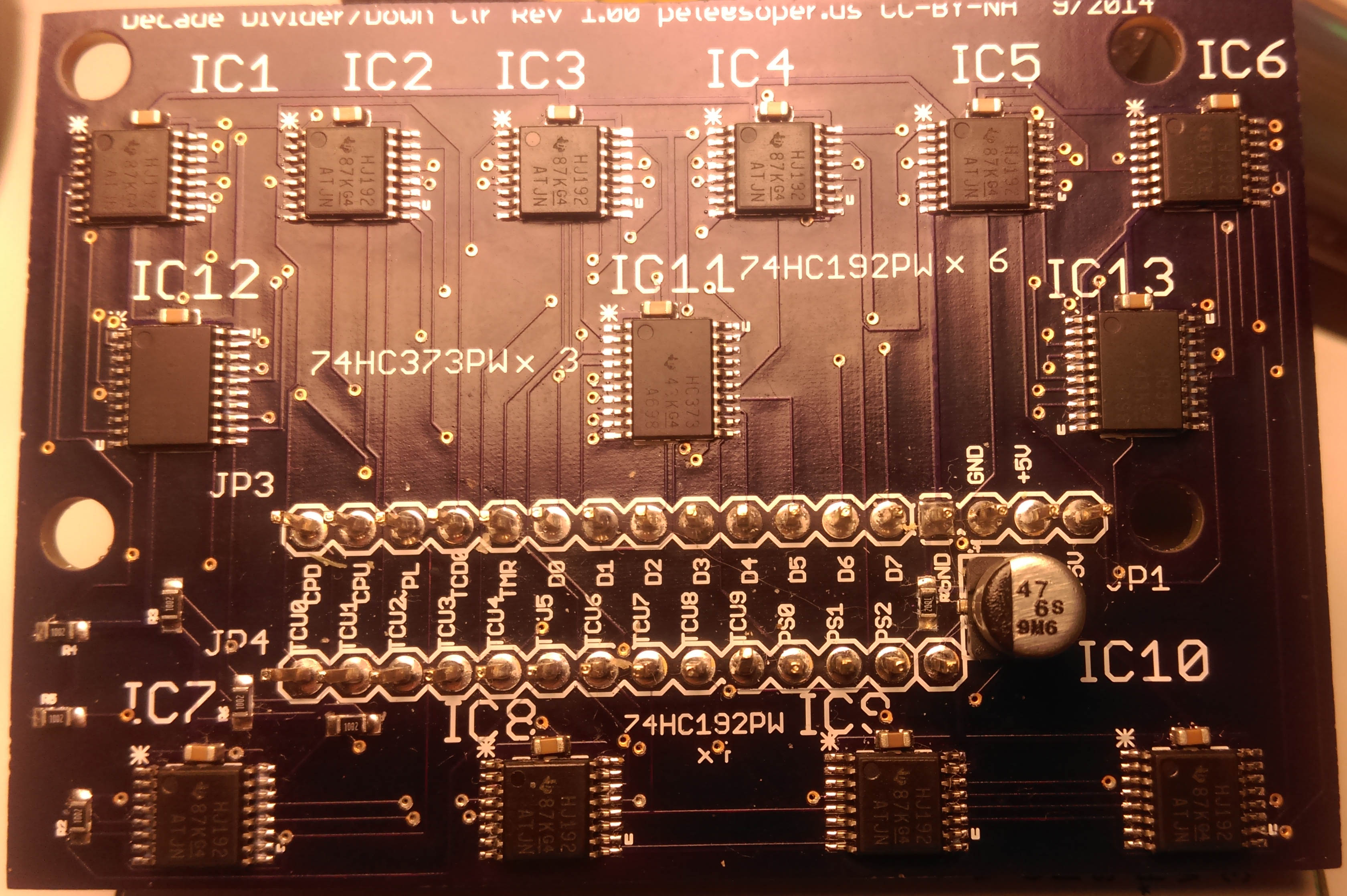
These four images above are the OSH Park top and bottom board renderings, the Eagle PCB rendering, and the assembled version of a 10 BCD digit synchronous counter. It counts in lock-step either up or down (i.e. no ripple-based indeterminacy except for carry-outs or borrow-ins) with the ability to reset all counters to zero or load the first six BCD digits via three latches fed by the main calibrator data bus (from a clock calibrator project). Using the presets a test clock input can count down to zero while a precision clock is timing the period needed to count N ticks of the test clock. In the other mode of operation a reference up count input such as the OCXO 10mhz reference up-counts the divider chain providing precise time base clock rates of from 10E6 to 10E-3 HZ.