Originally from https://imgur.com/gallery/FXb7ipm
Originally from https://imgur.com/gallery/FXb7ipm
I started having issues with my drip irrigation controller. It failed to turn off the other day. Luckily I caught it within a half hour, so things did not get too wet.
I have done some debugging and have isolated the issue to a digitalRead(14) line in my sketch that glitches with an unexpected value. This pin is enabled as an INPUT_PULLUP pin (internal pullup enabled) and is connected to a micro switch inside of the valve that controls the water. The switch detects whether the valve is open or closed. You can see why getting the wrong answer here would be problematic.
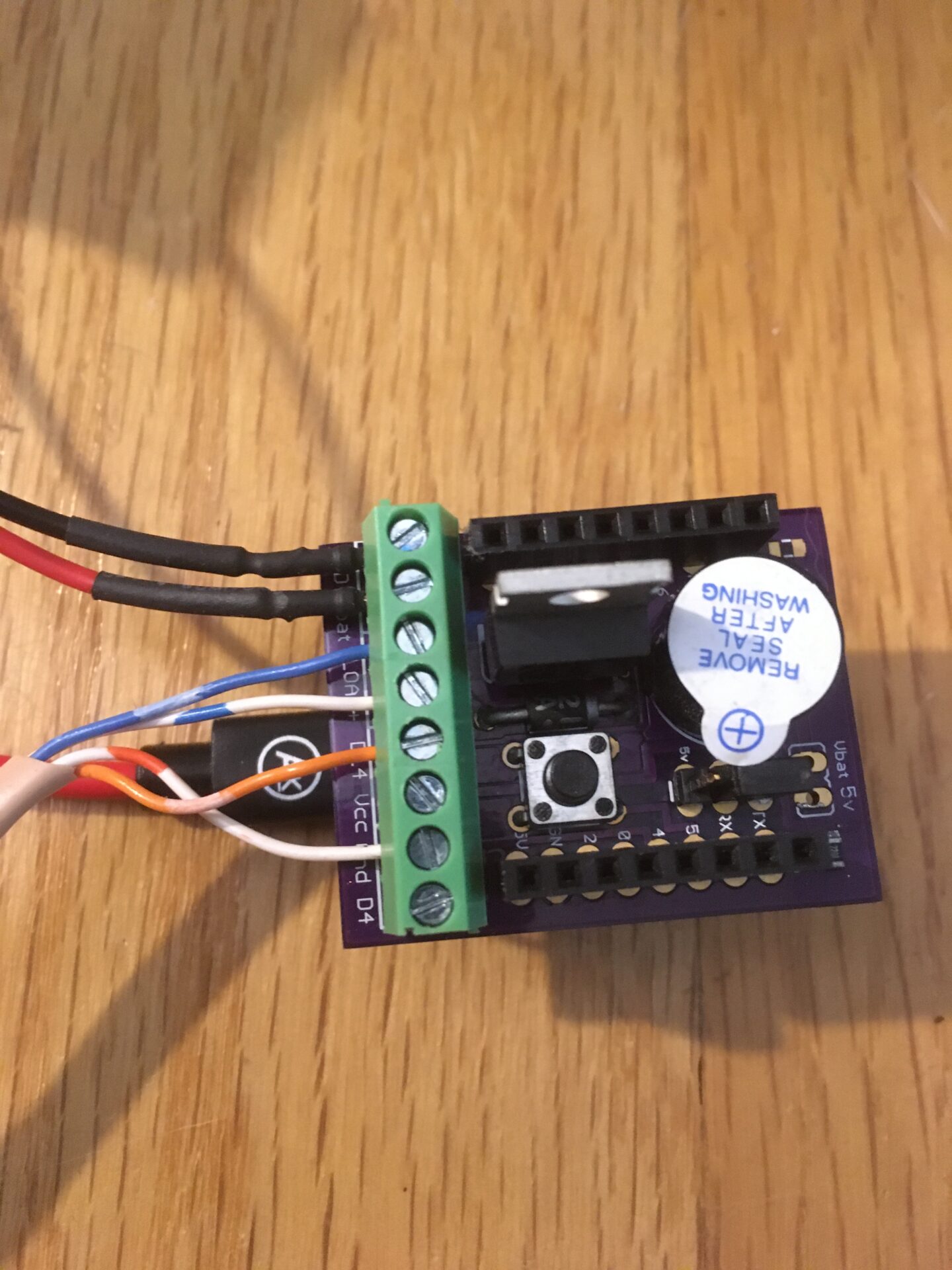
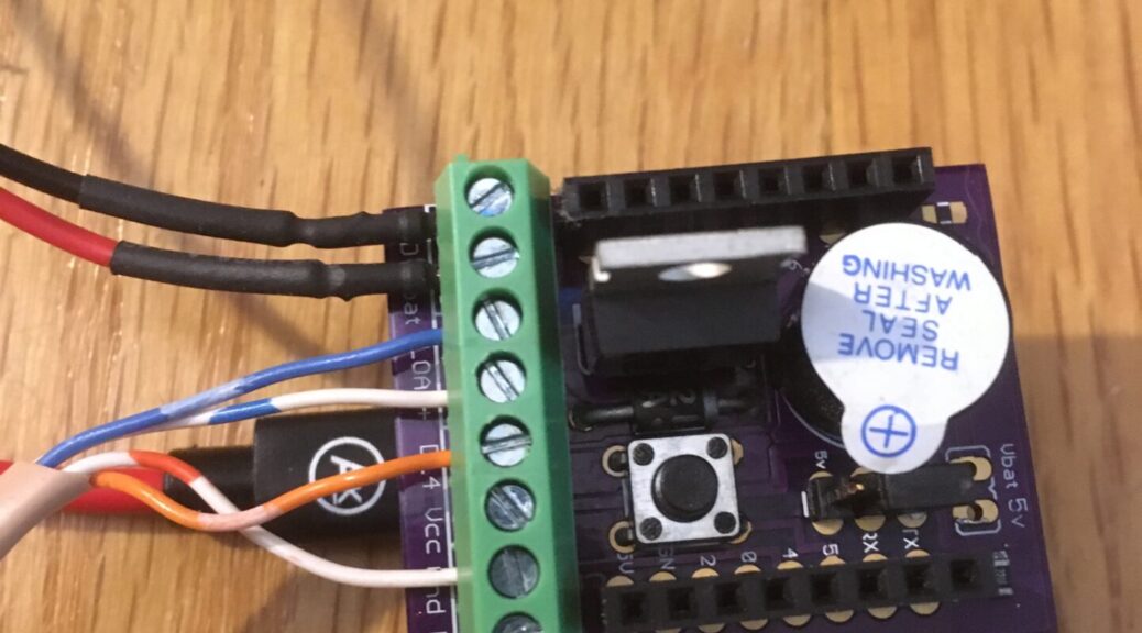
Additional HW details. I am using a D1 mini lite board (ESP8266 based). The D14 pin connects to a custom built shield which routes that signal to a screw terminal. From the screw terminal, the orange wire travels about 2 meters to the valve where it attaches to one contact of the switch. The other contact is attached to the white/orange wire which goes back to the screw terminal on the shield to ground. So, this switch grounds the D14 pin when it closes and allows it to float when open. The wire is some CAT3 telephone wire with orange and white/orange twisted together beside blue and white/blue twisted pair. There is no shielding wrap. The blue pair provides voltage (~3v from two D batteries) and ground to a DC motor in the valve to open/close the valve. The shield contains an N-mosfet to turn the DC motor on/off. I turn the MOSFET on via the ESP8266 and monitor the switch. The expectation is that the switch should turn on/off every 2-3 seconds as the valve rotates.
Here is some output from the sketch showing the valve working properly:
millis elaps b4 now lowcnt hicnt
119648: 2455: 0: 1: 26112: 00010: 0: valve 67
122532: 2884: 1: 0: 00001: 51929: 0: valve 68
125000: 2468: 0: 1: 26975: 00011: 0: valve 69
127955: 2955: 1: 0: 00001: 56393: 0: valve 70
130400: 2445: 0: 1: 25489: 00008: 0: valve 71
133308: 2908: 1: 0: 00001: 53400: 0: valve 72
135779: 2471: 0: 1: 27155: 00010: 0: valve 73
138576: 2797: 1: 0: 00001: 46387: 0: valve 74
141020: 2444: 0: 1: 25460: 00010: 0: valve 75
143929: 2909: 1: 0: 00001: 53475: 0: valve 76
146361: 2432: 0: 1: 24666: 00011: 0: valve 77
millis is the milliseconds since the ESP8266 booted. Elaps is the delta between consecutive millis lines. b4 is the old value of D14 and now is the new value. lowcnt is the number of times the signal was sampled low, while hicnt is the number of times the signal was sampled high. We can use the valve counter at the far right to talk about specific lines in the table. Valve count 68 shows a typical high to low transition. For 51929 samples, the signal was high. Then, it went low. We could draw this as:
———————–…———————|_
My software detects this falling edge and signals a transition. Valve 69 shows a typical low to high transition. Following the high to low transition detected by Valve 68, there is a debounce period (3 ms) during which we log, but ignore all values. During this period, there were 10 high values recorded (11 minus the one that we acted upon at the end) and an unknown number of low values. In total, there were 26975 low values and 11 high values. We could draw this as:
XXX_______________…__________________________|-
This switch rarely bounces on the transition from low to high and does bounce for about 500us on the high to low transition (see scope shots below).
Q1: Why are there roughly twice as many samples recorded while the switch is high? I do not have anything I can think of in the sketch that acts differently based on whether the switch is high or low…
Here is what things look like when we experience the glitch:
millis elaps b4 now lowcnt hicnt
146361: 2432: 0: 1: 24666: 00011: 0: valve 77
149294: 2933: 1: 0: 00001: 54987: 0: valve 78
149297: 0003: 0: 1: 00000: 00133: 0: valve 79
149339: 0042: 1: 0: 00001: 02717: 0: valve 80
151711: 2372: 0: 1: 20787: 00012: 0: valve 81
154665: 2954: 1: 0: 00001: 56310: 0: valve 82
157049: 2384: 0: 1: 21622: 00010: 0: valve 83
159873: 2824: 1: 0: 00001: 48085: 0: valve 84
Valve 78 looks normal, but it isn’t. After 54987 high samples, we got a low sample. We then enter the debounce period and after 3ms we get valve 79, with zero low values seen and 133 high values seen. This means that there was a single cycle low pulse at the end of valve 78 that made us think the switch had closed (pulled down to ground). After another 133+2717 high samples, we finally get the real low sample at valve 80. About 77{13079d06258ef9010cea88dee32f3cdfc6f216a54651010f7303ce6140ee927c} of the time, the glitch is a single low sample during an expected high section. About 23{13079d06258ef9010cea88dee32f3cdfc6f216a54651010f7303ce6140ee927c} are a single high sample during an expected low section. If I do two digitalReads in succession and see if they differ, I can create a trigger for my USB scope to capture these events.
Typical switch bounce on High to Low. The yellow signal is the D14 pin on the header of the custom shield. The red signal is the debug signal. You cannot see it, but there is a very short spike on the red signal at the vertical dotted line marked “T” for trigger. In this case, we sampled the signal as the edge was rising and got low followed by high.
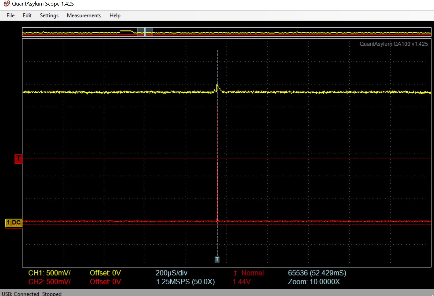
Unusual switch bounce on Low to High. Again, this was a sample of low followed by a sample of high. Not unexpected.
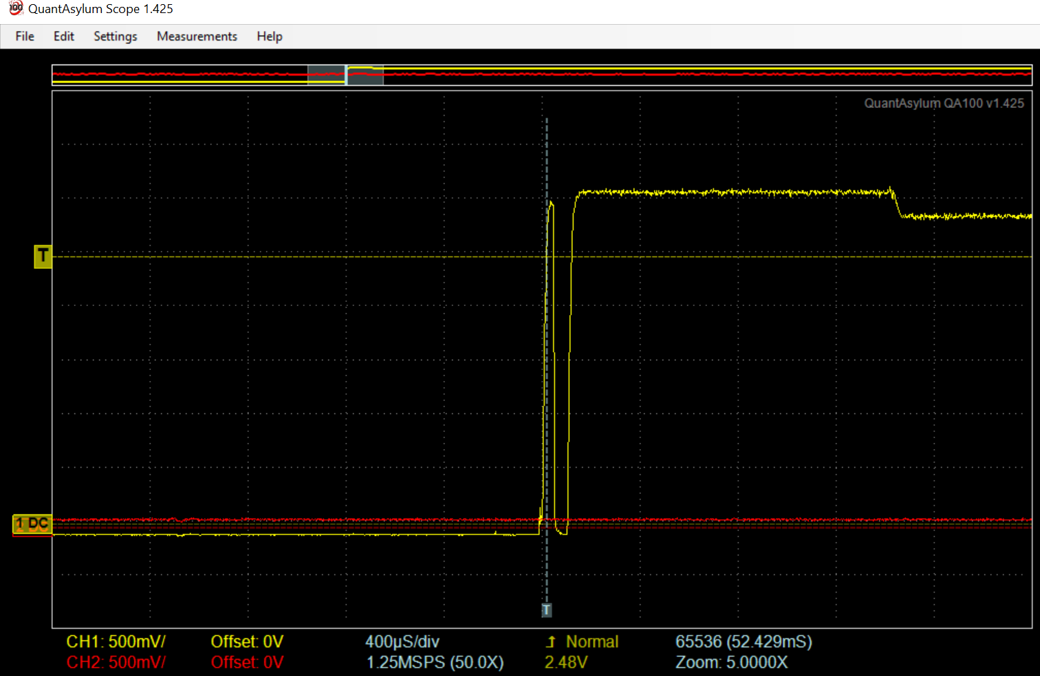
Q2: What is that wiggle in the signal toward the right edge here? The switch has opened, the internal pullup has worked, but then there is a drop of about 200mv.
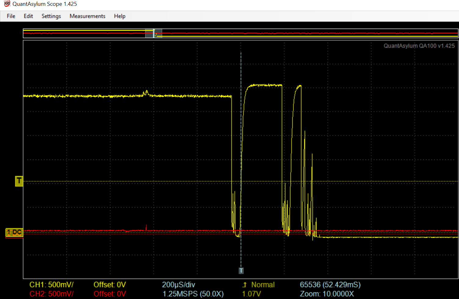
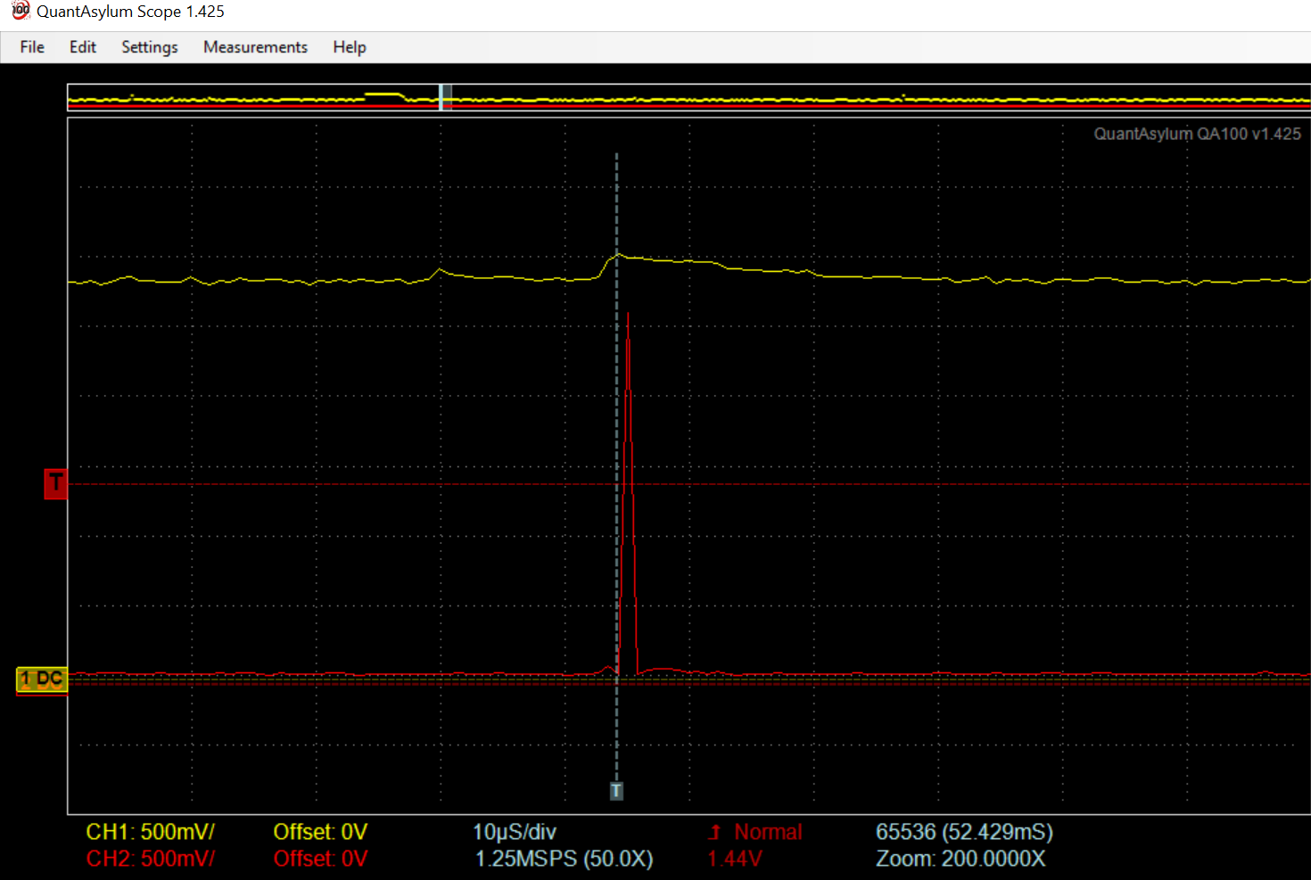
The Glitch. The red line pulses (saying we got different values from two successive digitalRead(14) calls. The yellow signal has a wiggle at the glitch, but there are other, much larger wiggles that do not exhibit the glitch. I show a zoomed in image as well. My scope is sampling at 1.25 MSPS.
Q3: What might be causing this? Is it interference from the DC motor? I have scoped the 3v power going to the motor (at the shield screw terminal) and it looks very clean.
Update 1 – May 24th
I tried replacing the D1 mini with another unit. The problem reproduces with the new unit. I unhooked the orange wire which goes from the screw terminal on the shield to the switch in the valve box. The problem reproduces. In other words, with nothing connected to the D14 pin, I still get occasional reads of LOW on that pin even though the pin is configured with the internal pullup enabled. I unhooked the white/orange unit from the shield and the problem still reproduces. All that remains connected to the shield is the battery (3V) and the motor.
Here is a schematic of the MOSFET shield I designed.

Update 2 – May 24th
The glitch is present when the DC motor is connected across VBAT and GND (bypassing the MOSFET). The issue occurs when the MOSFET is gated or ungated. I have not observed the glitch when the DC motor is not running.
Update 3 – May 26th
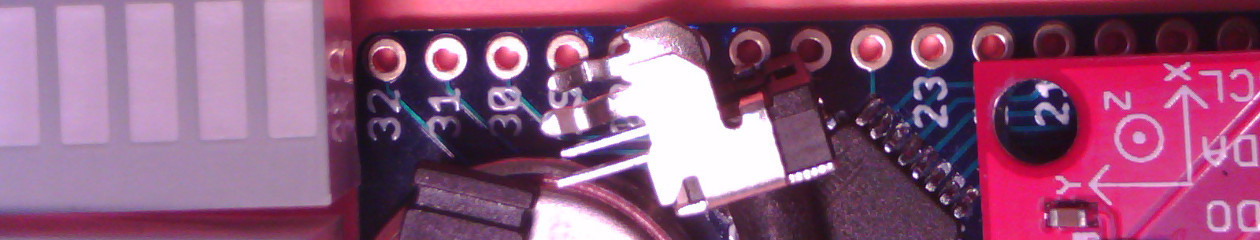
Summary: The issue happens with multiple D1 boards and multiple pins. DC motor has to be on. MOSFET does not need to be gated or in the circuit of the motor. Switch does not need to be connected, but with it connected, we seem to get more glitches. I ran a test polling GPI (ESP8266_REG(0x318)) watching for spurious changes to as many INPUT_PULLUP signals as I could configure on the board.
Single sample glitch test (a – b – a – a – a)
These pins were enabled as INPUT_PULLUP:
Pin 0 (0001) is not routed on the shield (glitches seen)
Pin 2 (0004) is not routed on the shield
Pin 4 (0010) is routed on the shield to a screw terminal
Pin 5 (0020) is routed on the shield to a switch (normally open)
Pin 12 (1000) is routed on the shield to the buzzer (glitches seen)
Pin 13 (2000) is not routed on the shield (valve switch connects here)
Pin 14 (4000) is routed on the shield to a screw terminal
0001: C035 C034 C035 C035 C035
0001: E035 E034 E035 E035 E035
1000: C035 D035 C035 C035 C035
1000: E035 F035 E035 E035 E035
2000: C035 E035 C035 C035 C035 <– could be switch bounce
2000: C035 E035 C035 E035 E035 <– could be switch bounce
2000: E035 C035 E035 E035 E035 <– could be switch bounce
3000: E035 D035 E035 E035 E035
Please add your comments below.
We will meet via Jitsi on Monday October 12, 2020 at 7:00 pm
Watch the mailing list (here) for the link to the meeting.
Agenda:
I have posted the slides for the two home automation presentations.
https://triembed.org/wp-content/uploads/2020/09/HomeAutomation.pptx
https://triembed.org/wp-content/uploads/2020/09/HomeAutomationPart2.pptx
… presentation have been posted here.
I created a page about my recent presentation with a link to the slides here. Video will be uploaded when it is ready. There is some explanation about the dropped characters we saw in demoB.
—> Paul MacDougal
I uploaded my powerpoint slides, Arduino library, and demo sketch here. I am sorry that we could not get video of the presentation.
—> Paul
I finished writing up my project for monitoring a golf cart battery pack. A very basic sketch with logging to the serial output. Cut and paste to Excel and make pretty charts… Look here.
—> Paul MacDougal
I posted slides and code for the examples from the Arduino Interrupt presentation I did on Monday, September 8, 2014. There was discussion after the presentation on how to sleep for an hour or a day or … I added another example to show one way to simulate a long sleep with multiple 8 second WDT interrupts.
—> Paul