From an issue of the amateur radio magazine “QST”

The normal meeting format will be followed (welcome new attendees, announcements, problem/design review of the month, presentation, community project status, show and tell). This month’s presentation will be by Nick Edgington of Edgington Labs. Nick will share details of a very inexpensive line of mixed signal FPGAs (initial breakout board coming from OSH Park). Additional meeting time will be devoted to the status of the TriEmbed Community “Espressif 32 bit processor board + FPGA(s)” development board project.


With the introduction of the Raspberry Pi Pico , “Raspberry Pi” can now be thought of as a brand with two distinct product types. The Pico board features a Foundation-designed chip on a small board only needing header pins, offering an inexpensive but very powerful and versatile microcontroller suited for applications where Linux is less well suited.
With two M0+ Cortex cores, six independent banks of SRAM totaling 254KB, support for execute in place (XIP) from up to 16MB of outboard flash (2MB on the Pico board) at up to 133MHz, and support for variable clock rate and novel programmable I/O control, this is not your everyday low-end Cortex board. Below is a list of links to more details about Pico, its processor chip, firmware, software and tool chain, as well as the complete collection of related source repositories. (1/26/2021: Some host platform-specific tools are also included now. Thanks, Mike Fulbright!).
Raspberry Pi Foundation introduction to Pico
Raspberry Pi Pico specs and list of resources and purchasing sources
GitHub repositories:
micropython
openocd
pico-bootrom
pico-examples
pico-extras
pico-micropython-examples
pico-playground
picoprobe
pico-project-generator
pico-sdk
pico-setup
pico-tflmicro
picotool
thonny-pico
Ubuntu 18.04 Cmake >= 3.12 available from https://apt.kitware.com
Latest ARM crossbuild environment: https://developer.arm.com/tools-and-software/open-source-software/developer-tools/gnu-toolchain/gnu-rm/downloads
Two events reminded me recently that you can’t have too many choices for solving a sourcing problem.
A client and I had finished a simple PCB design, got it off to OSH Park and OSH Stencils, and turned attention to the BOM. All passives but one: in my shop already, so check. The remaining one and some connectors: Digikey has them, so check mark. The central IC that is the point of the board: Digikey, zero. Mouser, zero. Other suppliers we’d heard of, zero. Anyplace in the USA, zero. China, only on breakouts. Ouch. Europe: “Rutronik”. Who? After a day of thrashing I noticed this is the chip manufacturer’s favorite distributor in Europe, and I should be able to trust them. I had to establish a business account but all was well until we got to shipping: Big ouch. And this huge minimum shipping wasn’t for Startrek teleportation beaming from their warehouse to my bench, as the fee implied. They predicted 72 hours, but later we found that was if you’re in the EU. Oh, right. When it wasn’t at my door in 72 hours I dug up an Excel spreadsheet via a well disguised link on my account page and on one row was a red “warning dot”. More digging and I decoded this warning to translate to English as ” six days estimated delivery from order date”. But the chips should be here in time for the reflow oven and all is well even if the client’s wallet is thinner than desired.
Just days later another client and I were deciding what parts of a new board really needed breadboarding to give us confidence in a major respin and this forced an immediate order of a few piddly parts (note to self: as soon as the part is on the short list for a design, order three of them.) I was inhaling to commiserate about shipping when the client reminded me that Arrow isn’t charging anything for shipping. Period. Zero, no matter what size the order is. I was startled, as this has been going on for months and I just assumed it was a one shot, short time thing and had let it fade from my memory. Instead I was able to throw the part number and quantity for a special FET I want to try out into the client’s order, smiling at the idea and my share of the shipping will be zero. Nice.
Meanwhile, the US rep for the big Euro distributor contacted me and we’ve agreed I will call her before risking another big wad on shipping that isn’t even fast in relation to the cost.
So, one arrow moved to the front of the quiver and a new one added for Euro parts that the US hasn’t discovered or that got too popular for supply here to keep up with.

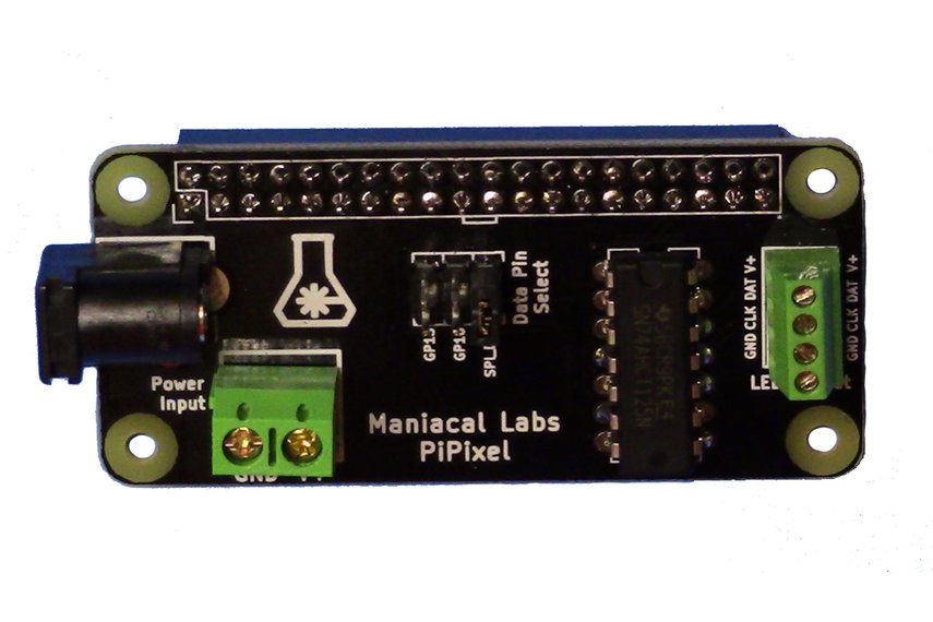
Adam Haile and Dan Ternes of Maniacal Labs have been busy. By accident I came across their site on Tindie and see they have a new product. PiPixel is oriented toward Raspberry Pi enthusiasts who would like to work with smart RGB LED strips. It’s described in detail on their web site. This is a super low cost kit that would make an excellent beginning soldering project with a big payoff. Find all the details on the ‘Labs web site.
A few notes from listening to Brent of OSH Stencils: on The Amp Hour:
Folks familiar with the OSH Park web site for ordering PCBs may not be aware of their blog site with virtual tons of user project information. Enjoy!
Just got this Aven 17010 Adjustable Circuit Board Holder from Amazon, but turns out it’s also Newark part 30Y9494. I love it already. Where has this been in my life? Etc. The above links show typical boards, but here’s a shot to show it works for the 40 cent OSH Park boards too:
This is a constant current dummy load made from one of Shane Trent’s PCBs like those given away at a recent TriEmbed meeting. As mentioned on the email list, this PCB is a “fixed” version of a design from a “Sleepy Robot” blog of a guy named Wittenberg, which is itself a derivation of an original design by Dave Jones of EEVblog. Wittenberg had made available gerbers for his design (in early 2012) that were unfortunately defective, and he didn’t allow for two way communication, forcing Shane to go to great lengths to correct the gerbers and get a run of PCBs fabricated. Shane’s blog article covers all this in depth and has a link to the corrected gerber files in zip format.
Fast forwarding to the present, here’s a recent tutorial by Dave going into depth about battery measurements. Viewers will just have to put up with the axe-grinding, horse-beating treatment of a “battery life extender” Kickstarter that pushed Dave’s buttons. Apart from this, it’s an excellent treatment and a fantastic “essential subset” spreadsheet tutorial for folks that just want a hint about how to do cool things like the graph-making done in this video.
I assembled and tested a second of the PCBs recently. It will sink up to one amp at up to around the 60 volt limit of the FET used (MTP3055VL) HOWEVER, unless you like to see magic smoke the 18 watt thermal limit of the FET/heatsink assembly has to be honored. So at a full ampere the voltage limit is around 18, and at that load be sure to avoid touching the transistor! At one ampere the shunt resistor will be operating at it’s rated dissipation limit and will also be very hot. To summarize, this load has to be kept at an amp or less and at 18 watts of power dissipation or less. (Note: the shunt resistor is temporarily 5{13079d06258ef9010cea88dee32f3cdfc6f216a54651010f7303ce6140ee927c} tolerance due to an ordering blunder. That will be fixed.)
I’ve decided to make it available for borrowing by TriEmbed meeting attendees who can guarantee it’s return by them or their designee at the following month’s meeting. The transistor is not expensive and it won’t be any big disaster (just embarrassing) if it’s accidentally destroyed, but blowing the traces off the PCB will be frowned upon (joke). So this (and perhaps some of the TriEmbed contact cards Paul made, hallway signs, etc) could be part of a shared resource that could expand over time.
The “UI” is currently two voltmeter test points, with the unit showing the load current as a one to one mapping from amperes to volts. A digital display with simple USB serial (current and “external voltage” aka battery voltage) logging output and some temperature compensation/auto-calibration is planned, but it would be straight forward to tie the test points to something like an Arduino analog pin or two.
Remotely controlling and/or making the current limit programmable would be a bit harder, but a properly coordinated hack to provide an alternative control mechanism would be OK with me and make for a fun project for somebody.
Here are all the design-related links in one place:
Here are some BOM changes: