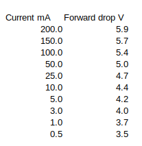
Sometimes we’re faced with a situation where a single DC supply is all that’s available but it’s is too much for part of a system and we really wish we had a lower voltage too. I knew diode forward voltage drop is a function of current (and temperature), but I didn’t appreciate just how variable this was until I got lazy and failed to look at a datasheet before I strung some 1N4148 diodes in series as a quick and dirty way to knock 12 volts down to nine. I figured that with the “standard” voltage drop across a silicon junction being .6 volts then 6x.6 = 3.6, and I knew if the current variation gave me around nine volts that would be OK for my application. Except when I tested this I found the variations at the currents the application involved would be all over the map. Here’s a table of what was measured across the six diodes at different values up to the absolute max current for the device:

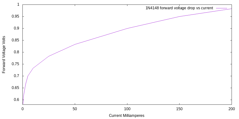
Here is the same data but for a single diode:

So the per-diode voltage drop is only close to the .6 volts cited for silicon junctions at around one milliampere of current. At the upper current limit of the diodes the drop is very much higher. My application spanned a wide range of currents, so this diode string was hopeless (the client might have noticed a slight behavior change depending on operating mode, and I couldn’t tolerate that.) In my defense over the years I’ve treated diode voltage drops as something I wanted to minimize, making me not just a schottky diode bigot but one who would spend a hour finding the absolute lowest forward voltage drop for a given current. But I obviously developed no intuition at all for the more general cases.
Luckily I found a 7809 linear regulator in my junk box and I can simply carry on without having to order a part, but I thought this might be interesting to share. A high enough power zener would have been another solution.
As mentioned at the beginning, diodes change their behavior with temperature changes too and this is why you sometimes see a diode clamped under or near a power transistor: it’s change in behavior is leveraged with circuitry to keep the transistor from operating outside its safe temperature range. And some folks are able to use tables or perhaps a Taylor series with firmware to monitor voltage drops and use their simple diodes as thermometers.

The standard diode equation if you rearrange it a bit will tell you that a diode Vbe will change about 60 mV per decade of current. If you multiply this by 6 you get 360 mV which is a lot. So from 1 mA to 100 mA, you could expect a 700 mV change which is what you’ve got. Semtech made these things called EZ Dropper’s that were a two terminal device that dropped a fixed amount over a pretty wide current range. (5 to 250 mA). The most popular was one that could drop 1.7V that could get you from 5 to 3.3v. They made adjustable ones too where you hung a couple of resistors on it and multiplied its 1.25 drop but the R ratio. They were kind of popular in very low cost things but the problem was that they had no load regulation- a 5+-10{13079d06258ef9010cea88dee32f3cdfc6f216a54651010f7303ce6140ee927c} supply turned into a 3.3 +- 20{13079d06258ef9010cea88dee32f3cdfc6f216a54651010f7303ce6140ee927c} supply after you subtracted 1.7v. I don’t know if they made HV versions- I only remember the 5 to 3.3. You’d think that a single white LED that drops 3.5v could get you going but they have about the same change as 6 diodes in series. Damn physics- just can’t get around it!
Thanks, John. Nice to get some expertise on the subject, and you’ve given us a rule of thumb that will be very useful.