With the introduction of the Raspberry Pi Pico , “Raspberry Pi” can now be thought of as a brand with two distinct product types. The Pico board features a Foundation-designed chip on a small board only needing header pins, offering an inexpensive but very powerful and versatile microcontroller suited for applications where Linux is less well suited.
With two M0+ Cortex cores, six independent banks of SRAM totaling 254KB, support for execute in place (XIP) from up to 16MB of outboard flash (2MB on the Pico board) at up to 133MHz, and support for variable clock rate and novel programmable I/O control, this is not your everyday low-end Cortex board. Below is a list of links to more details about Pico, its processor chip, firmware, software and tool chain, as well as the complete collection of related source repositories. (1/26/2021: Some host platform-specific tools are also included now. Thanks, Mike Fulbright!).
(Notes by Paul MacDougal with some light editing by Pete and Jenny Soper. A volunteer for February notes is needed.)

Problem Of The Month (P.O.T.M.)

Paul MacDougal reviewed  his long history of making some kind of puzzle to give to his nieces. A last minute flash of inspiration resulted in a maze in which two "pointers" following identical mazes were modified to be two "pointers" following different mazes. This requires the pointers to be able to move relative to one another. Controlling this movement and creating  compatible mazes induced development of software for creating and manipulating mazes. The "problem" this month was to suggest new features for this maze software.

Code Review Of The Month (C.R.O.T.M.)

Carl converted Paul's short python script to a class-based implementation. There was some discussion of Paul doing a sys.exit(x) from within a script that is running separate threads and how that might mess up. "FOO" vs "foo" vs "_foo" vs "__foo" conventions in Python. (And let's not forget "Foo"!)

Presentation:  ESP8266 OTA by Paul MacDougal

ESP8266 supplier Espressive has done all the hard work to use Over The Air firmware/data update (OTA) in its libraries. Paul showed a simple sketch to do OTA from the Arduino IDE which is just running a python script. Multicast DNS (mDNS) is used for identifying development boards via name rather than IP address. A simple sketch to do OTA by connecting to a device using HTTP was shown. There was discussion of using ports 80 vs 8080 (really < 1024 vs > 1023). A simple sketch to do OTA by device accessing a server at a known IP address was shown and there was discussion of security (or lack thereof) of OTA programming.
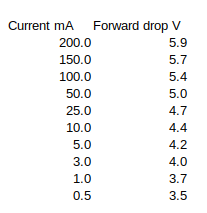
Sometimes we’re faced with a situation where a single DC supply is all that’s available but it’s is too much for part of a system and we really wish we had a lower voltage too. I knew diode forward voltage drop is a function of current (and temperature), but I didn’t appreciate just how variable this was until I got lazy and failed to look at a datasheet before I strung some 1N4148 diodes in series as a quick and dirty way to knock 12 volts down to nine. I figured that with the “standard” voltage drop across a silicon junction being .6 volts then 6x.6 = 3.6, and I knew if the current variation gave me around nine volts that would be OK for my application. Except when I tested this I found the variations at the currents the application involved would be all over the map. Here’s a table of what was measured across the six diodes at different values up to the absolute max current for the device:
Forward voltage drop across six 4148 diodes vs current
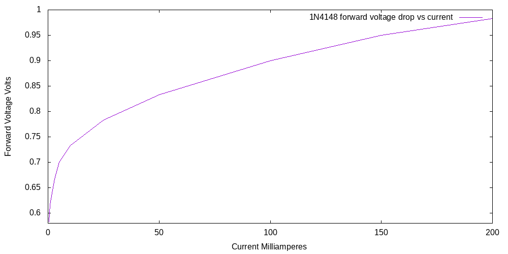
Here is the same data but for a single diode:
So the per-diode voltage drop is only close to the .6 volts cited for silicon junctions at around one milliampere of current. At the upper current limit of the diodes the drop is very much higher. My application spanned a wide range of currents, so this diode string was hopeless (the client might have noticed a slight behavior change depending on operating mode, and I couldn’t tolerate that.) In my defense over the years I’ve treated diode voltage drops as something I wanted to minimize, making me not just a schottky diode bigot but one who would spend a hour finding the absolute lowest forward voltage drop for a given current. But I obviously developed no intuition at all for the more general cases.
Luckily I found a 7809 linear regulator in my junk box and I can simply carry on without having to order a part, but I thought this might be interesting to share. A high enough power zener would have been another solution.
As mentioned at the beginning, diodes change their behavior with temperature changes too and this is why you sometimes see a diode clamped under or near a power transistor: it’s change in behavior is leveraged with circuitry to keep the transistor from operating outside its safe temperature range. And some folks are able to use tables or perhaps a Taylor series with firmware to monitor voltage drops and use their simple diodes as thermometers.
We will meet via Jitsi on Monday October 12, 2020 at 7:00 pm Watch the mailing list (here) for the link to the meeting. Agenda:
Welcome
Announcements
P.O.T.M.
Code Review Of The Month: A new feature. Carl Nobile will be reviewing some Python code each month to show proper style and features of Python. If you have some code you would like reviewed, send Carl an email
Mini Presentations:
InfluxDB and Grafana – Paul MacDougal
Kodak slide to jpg thumbnail project progress – Paul MacDougal
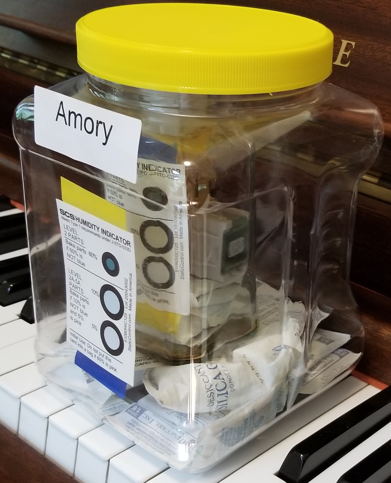
This is about assembling five PCBs yesterday that shared an IC and how, despite meticulous application of solder paste, reflow profile, yada yada, two of five didn’t pass FAT (final assembly test via a simple computer program and microprocessor). Late in the day a little light bulb glowed with faint neon letters spelling “popcorn.” This is the slang for when trapped moisture in an IC explosively changes to steam in the reflow oven, physically damaging the part. The part in question had been away from desiccants for months, the humidity in the shop is far from Arizona levels, etc. I don’ t have the equipment to determine if this damage happened, the budget involved can’t cover sending the board off to be studied, etc, so I just have to assume this is a “maybe” cause of my failures.
So I followed the specs for “baking out” the moisture and set up these chips with some others that need to stay dry or be in line for baking out and thought I’d share a snapshot. (Click on it to get a better version, and click on that for full resolution. The inner card color dots are distorted: they are actually blue). You know how we get desiccant bags and moisture card from places like DigiKey and toss them? I saved enough over the years to combine them with a cat treat container and Indian sauce jar to make a two level dry air environment. All the bags and some of the chips went through the bake out process (I used 125C for 12 hours). The outer card will let me judge how well the cat treat container lid fits and the same for the card inside the sauce jar with its tighter lid. Access is pretty easy and there is room for a “next gen” larger inner container down the road. The parts are in plastic boxes with labels facing out so I can quickly determine what’s there, and a few notations are on the box stickers to indicate their status wrt baking. (My parts database uses US town names starting with “A” for containers, thus the “AMORY” sticker).
I’m assembling several more of the same PCBs today and it would be nice if Whammy Central allows for pop-corning to have been the cause and the new boards to all pass FAT!