Open standard for connector/wire-free charging adopted by major car manfacturers

Open Dots Compatibility Logo


Ford, Chrysler, RAM, Dodge, and Scion have embraced an open standard for conveniently recharging portable devices that appears to be more effective and just easy to use as inductive charging systems. It’s called Open Dots.

The basic idea is to use a set of four parallel conductive strips to carry positive and negative voltages (or +V and ground, depending on your point of view) and have the package of a device to be charged connect to the charging strip automagically just by resting on it. The device to charge has a pattern of four conductive “dots” on its case that will properly connect with the charging pad in any orientation. This scheme was invented for recharging toys in 1963.

I’m sharing this as a potentially handy way to deal with the general problem of recharging battery-operated gadgets. It would take a fair amount of work to implement the pieces and parts involved with the actual electrical connections, but based on  the specification this is on the other end of the scale from rocket science and one would hope that the basic components may be or become cheaply available if the auto industry is involved .

As far as I can tell from their web site anybody could freely use these circuits and connector specs without consequences. (In order to sell something using the Open Dots logo one would need to execute and abide by a member agreement. But you do not need to get within a mile of this logo and could simply use the specs and reference circuits freely until you start selling a ton of stuff and see an advantage to becoming “official”.)

(Open Dots logo used without permission.)

May 11th Meeting 7PM @ NCSU

This meeting will have a handful of short presentations,  the usual show and tell, face to face networking and hands-on project help. Maps and additional details here. Planned:

  • Switch de-bouncing (Paul MacDougal)
  • Gathering ideas for an “Embedded Software Engineering 101” course (Christopher Svec)
  • Trivially solving arbitrary resistor networks with multiple voltage sources using Thévenin’s Theorem (Pete Soper)
  • <your very short presentation goes here>

(Pete and Christopher might possibly be on the road or late getting back into town, so their talks are tentative)

Upcoming monthly TriEmbed meetings at NCSU

  •  The May 11th meeting is open to some short presentations, ideally relevant to the recent “learning curve” list discussion. So far there already planned is a short switch-debouncing tutorial by Paul MacDougal and (if his flight isn’t delayed) a very short how-to by Pete Soper for using Thévenin’s Theorem to  solve nasty resistor network/mixed voltage source problems like the one in the XKCD Circuit. Also, if he’s not on the road with his job Christopher Svec  will give a short talk and open the floor for ideas for the “Embedded Engineering 101” course he’s mentioned on the email list.
  •  The meeting room assignment request is in for June/July/August, and it was early enough that we might hopefully keep the same room. With luck we’ll get the assignments in time to announce them at the May meeting.
  • June 8th will be focused on Craig Cook’s experience with an edX embedded systems course offered by U of Texas/Austin.
  • July 13th will feature Adam Haile and Dan Ternes of Maniacal Labs providing an update about their AllPixel project along with whatever else they’d like to discuss (perhaps some discussion with their co-conspirators about lighting up windows in downtown Raleigh?)

If you’re interested in giving a (short) talk in May or a talk at another TriEmbed meeting the best starting point is the TriEmbed email list (or, if it would be more comfortable, a message to Paul MacDougal and Pete Soper). You would ideally include a short synopsis and bio and conservative estimate of the amount of time you need.

TI Regrooves the MSP430?

(This is the moral equivalent of a press release that is not based on anything remotely official from TI. I know NOTHING beyond what I’ve read about this subject along with a smattering of MSP430 experience. I’m sharing this because I think it might be of interest to the TriEmbed community.)

Texas Instruments has introduced a new family of microprocessors called the MSP432.  As far as I can tell they’ve combined the very sophisticated power saving modes and mature peripheral functional blocks of the MSP430 family with an ARM M4F core.  I’m writing this because the initial chips are available in a QFP package.

The initial chips come with a couple of generous flash memory/RAM sizes combinations and run at 48mhz. Claimed integer MIPS/MHz are substantially higher than with the MSP430 and current consumption from the datasheet is only 90uA/MHz. But these are probably marketing MIPS and most assuredly marketing microamperes, as they understandably assume little or no peripheral subsystem activity. (Take it from me, you can get any result you want from the Dhrystone benchmark with a good compiler).  Still, to the extent that the MSP430’s programmatic support for low power modes is present in spades with a new “power manager” function, and the fact that the chips come with ROM-code peripheral libraries to make porting from the 430 easier, this seems to be an interesting development. I view this as a smart, if not surprising move by TI.

Additional info:

TI Info page

MSP432P4xx Technical Reference Manual

MSP432P401x Mixed Signal Microcontrollers Data Sheet

Wi-Fi Connected IOT Thing

I have been working on this IOT thing for a while and wanted to share some details of my latest project.   In using the data loggers, I have found that just as I need to be able to use different sensors, I also need to be able to support different methods of recording and reporting data.  My first data logger used a MicroSD card for disconnected data collection.  Then, I built a version which connected using a cellular network.  For this next version, I used WiFi.

I started this project using the Atmel 328p but soon came to a realization, with WiFi, I needed more working memory and would need a more powerful chip.  After some trial and error, I decided to use the wonderful Teensy 3.1 from PJRC.  This is an Arduino compatible ARM processor with much more memory and speed.

The basic build contains the following components:

The basic idea is that this board will connect to GPS, obtain a GPS fix and report its location to Ubidots.  Ubidots can then display this information in a number of ways including showing the location and the number of times the sensor had been moved that day as the dashboard below shows:

Screen Shot 2015-03-02 at 11.57.05 AM

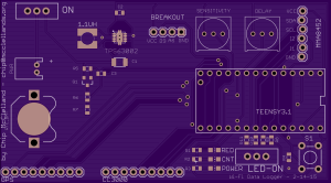
Here is the carrier board in detail:

Teensy Data Logger Board

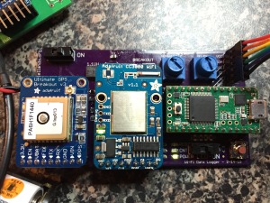
Here is what the basic board looks like:

Basic Board
Basic Board

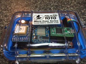
And here it is inside its protective Pelican case:

IMG_3919

I have posted the firmware sketch and the carrier board Design files to my Github repository.

A few design notes:

  • I wanted to use a variety of power sources (including Solar) so I went with the TI TPS63002 Buck-boost switching DC-DC converter.  It can be a pain to solder (see tutorial here) but I have yet to find a more versatile power supply.
  • I incorporated a very cool battery monitoring approach using a P-MOSFET to allow the data logger to monitor battery voltage and report it to Ubidots.  While not as good as true fuel gauge, it should be easy to implement across various power sources.  Thanks to Shane Trent for sharing this circuit on his excellent FET Tricks Blog.  I have yet to implement this in the firmware but will leave that you to.
  • I have put some potentiometers and a momentary contact switch (held high) on the board for future use.  One plan I have for the switch is to test for a button press at startup to select the WiFi network to use.  The potentiometers are intended to adjust the sensitivity and reporting interval for the logger.
  • I added extra connections for power management – you should be able to turn off the WiFi and GPS modules to save power between reporting.  The Teensy can be put to sleep as well and the accelerometer can wake it with the provided interrupt connection.
  • I also included the battery holder and header pin for using the Teensy’s integrated real time clock.  You only need to add the battery and solder a crystal on the underside of the Teensy.  This would enable you to set a regular reporting interval even if no movement is detected. Full instructions are provided here.

I hope this information is helpful.  Please leave comments or contact me if you have questions.  Also, you can follow me on Twitter @chipmc86 to hear about more over time.

Chip


Triangle Embedded Interest Group