September 14th 7-9pm Meeting Details

This month’s meeting on the  NCSU Centennial Campus will be back in Engineering Building I, room 1005:    Meeting Details & Maps

Currently scheduled for this meeting:

  • Ohm’s Law Modeled With Fluid Flow by Ryan Schuster
  • More Ohm’s Law by Kevin Schlif

The last part of the meeting will be the usual open forum and face to face networking. Bring your show and tell items, problems needing help, etc.


For the August 10th Meeting: Electronics Tutorials & A Bench Test Instrument

This month’s meeting will be at  NCSU Centennial Campus Engineering Building III:    Meeting Details

The August meeting will be in three parts:

  • Ohm’s Law Modeled With Fluid Flow by Ryan Schuster
  • Transistor Tips by Shane Trent
  • A Programmable Bench Test Instrument Oriented Toward Power Measurements by Chip McClelland

The last part of the meeting will be the usual open forum. Bring your show and tell items, problems needing help, etc.


Battery Testing Resources

LoanerDummyLoad

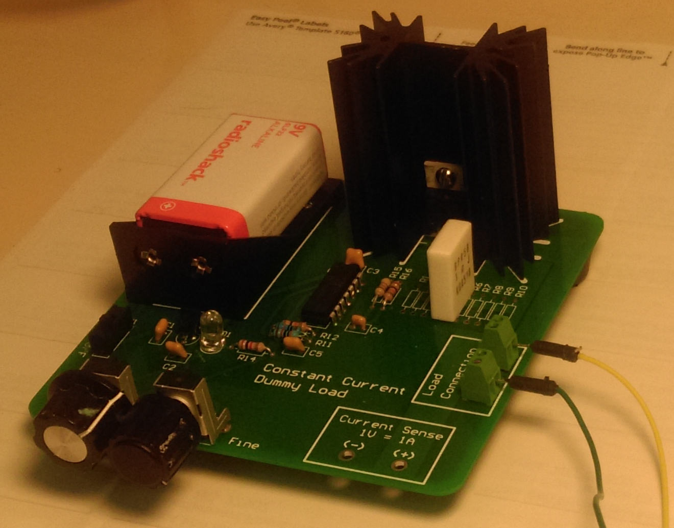
This is a constant current dummy load made from one of  Shane Trent’s  PCBs like those given away at a recent TriEmbed meeting. As mentioned on the  email list,  this PCB is a “fixed” version of a design from a “Sleepy Robot” blog of a guy named Wittenberg, which is itself a derivation of an original design by Dave Jones of EEVblog.  Wittenberg had made available  gerbers for his design (in early 2012)  that were unfortunately defective, and he didn’t allow for two way communication, forcing Shane to go to great lengths to correct the gerbers and get a run of PCBs fabricated. Shane’s blog article covers all this in depth and has a link to the corrected gerber files in zip format.

Fast forwarding to the present, here’s a recent tutorial by Dave going into depth about battery measurements.  Viewers will just have to put up with the axe-grinding, horse-beating treatment of a “battery life extender” Kickstarter that pushed Dave’s buttons. Apart from this, it’s an excellent treatment and a fantastic “essential subset” spreadsheet tutorial for folks that just want a hint about how to do cool things like the graph-making done in this video.

I assembled and tested a second of the PCBs recently.  It will sink up to one amp at up to around the 60 volt limit of the FET used (MTP3055VL) HOWEVER, unless you like to see magic smoke the 18 watt thermal limit of the FET/heatsink assembly has to be honored. So at a full ampere the voltage limit is around 18, and at that load be sure to avoid touching the transistor! At one ampere the shunt resistor will  be operating at it’s rated dissipation limit and will also be very hot. To summarize, this load has to be kept at an amp or less and at 18 watts of power dissipation or less. (Note: the shunt resistor is temporarily 5{13079d06258ef9010cea88dee32f3cdfc6f216a54651010f7303ce6140ee927c} tolerance due to an ordering blunder. That will be fixed.)

I’ve decided to make it available for borrowing by TriEmbed meeting attendees who can guarantee it’s return by them or their designee at the following month’s meeting. The transistor is not expensive and it won’t be any big disaster (just embarrassing)  if it’s accidentally destroyed, but blowing the traces off the PCB will be frowned upon (joke). So this (and perhaps some of the TriEmbed contact cards Paul made, hallway signs, etc) could be part of a shared resource that could expand over time.

The “UI” is currently two voltmeter test points, with the unit showing the load current as a one to one mapping from amperes to volts. A digital display with simple USB serial (current and “external voltage” aka battery voltage)  logging output and some temperature compensation/auto-calibration is planned, but it would be straight forward to tie the test points  to something like an Arduino analog pin or two.

Remotely controlling and/or making  the current limit programmable would be a bit harder, but a properly coordinated hack to provide an alternative control mechanism would be OK with me and make for a fun project for somebody.

Here are all the design-related links in one place:

Here are some BOM changes:

  • The load connection is just four bare plated through holes intended to get some wire loops. These Newark  12H8386  screw terminals solder in and work well.
  • As mentioned, a momentarily loose screw resulted in this Mouser part 660-MF1/4DCT52R10R0F  five watt resistor being substituted for the default 10 1/4 watt resistors. The bad news is this resistor has a 350ppm/C coefficient as well as being only 5{13079d06258ef9010cea88dee32f3cdfc6f216a54651010f7303ce6140ee927c} tolerance.  A better choice than either might be a pair of three watt, two ohm 1{13079d06258ef9010cea88dee32f3cdfc6f216a54651010f7303ce6140ee927c} Vishay resistors such as Mouser 71-RS02B2R000FE12. These have 50ppm/C coefficient so there would be about another 1/2{13079d06258ef9010cea88dee32f3cdfc6f216a54651010f7303ce6140ee927c} error at the point you could boil water on them.

For the July 13th Meeting: An AllPixel Project Update

The July meeting will be an update about the AllPixel project, a USB-based smart LED controller launched via KickStarter last October by Adam Haile and Dan Ternes of Maniacal Labs.

In addition Ian Hands will demonstrate his (simulated) garage door + sparkcore + Pebble + Ubidots project and update us about geekSPARK in September.

Short tutorials about basic electronics would be welcome.


Cary/Crossroads Radioshack just another crummy example now

In an apparent about face the Cary Crossroads Radioshack is now missing almost all the stuff that had kept it a huge exception to the rule up to this point. The repair shop is gone, the wall of Littlebits is gone, everything to do with soldering except a few temp controlled irons is gone, all the plastic boxes, perf boards, and other stuff to do with building things is gone, and the wad of Arduino-related stuff is gone except for a few lonely Arduino boards and a shield or two on the near end of the back. Much quizzing of the staff suggests their supply chain is now a hypothetical construct. Quoting Porky Pig, “That’s all, folks!”


EveryCircuit: Chrome killer app for electronics enthusiasts

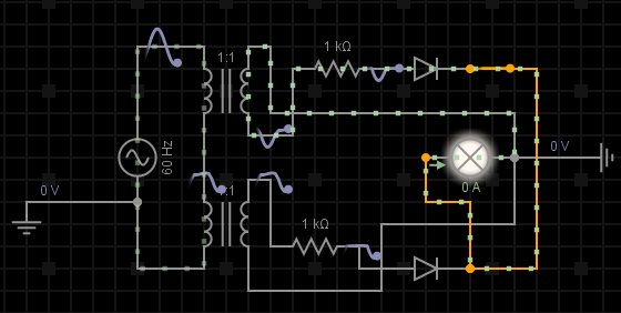
everycircuit.com-circuit-6343833974472704-full-wave-rectifier-

I recently added an app to my smart phone and, as a side effect, added another app, and  that led me to stumble upon the web site http://everycircuit.com, which provides electronic circuit editing/simulation/presentation tools together with commercial and crowd sourced example circuits.

For those whose religious convictions or practical circumstances make Chrome available on a laptop/desktop, the rest of this page might be interesting. Likewise, if you have a spare $10 the Android or IPhone apps might be interesting. So far, the Android version “just works” on my phone and I personally rate it “Uh, I’ve got to put my socks back on.”  Finally reading the site’s terms of use use might be a good idea for some people. I carefully read every word, something I rarely do. But I was relieved to see that the EveryCircuit people (currently) appear to stop short of claiming copyright on crowd sourced circuits.

To check this site out, try this link to the user-submitted rectifier circuit example above inside an instance of the Google Chrome browser on a desktop or laptop computer:

Visit rectifier example

Now  click the moving squiggle in the upper left. It expands to a pretend oscilloscope showing voltage and current vs time for one part of the circuit.

Now click the “edit this circuit” link. There are tools for modifying this circuit.

Cool, heh? The main site page is here.

Yes, again, this tool isn’t supported in many, many settings that readers of this blog find themselves in. It’s completely dependent on Chrome.  On behalf of the company owning this site (that I just found: I have no connection to it), I’m sorry it isn’t more portable.

By the way: Anybody reading this is welcome to submit their impressions of this or anything else here as comments below. TriEmbed meeting attendees or their online friends (such as in Vermont) are invited to request a blog account if they have interest in adding content to this site via blog postings, additional project pages, etc. Your access  will be proportional to how well you’re known to the admins and editors (but we’re always looking for new editors and at least one additional admin!) It takes about 10 minutes with somebody who is WordPress fluent to learn how to add content.

Low Voltage MOSFET Transistors

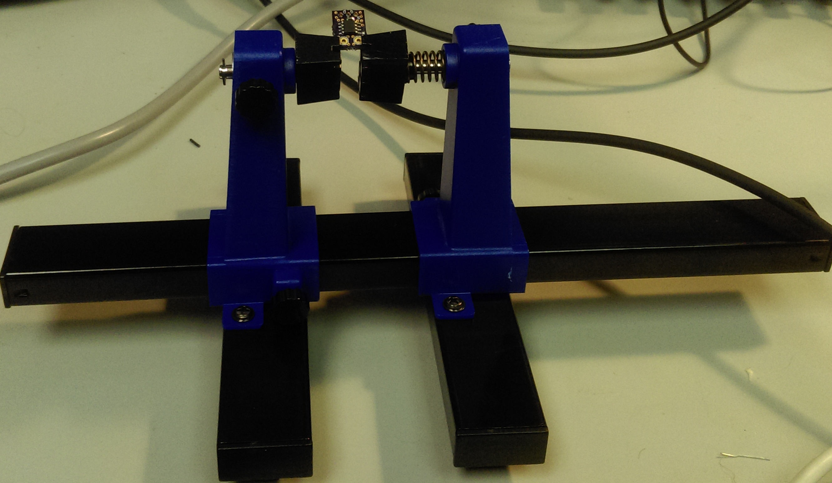
Shane Trent recently shared some recommendations for MOSFET transistors in SOI8 packages that will switch to saturation with ordinary logic level signals.  The two transistors he mentions are inexpensive, offer low on resistance, and would seem to be perfect for prototyping, except for one detail. Off the shelf SOIC8 breakout boards such as this one from Adafruit are designed for small signals and modest power supply currents. The N channel part Shane recommends can handle enough current in pulse mode to demonstrate the Adafruit board traces as fusible links. On the other hand, anything beyond a small number of amperes is asking trouble with a breadboard. (For higher power situations Shane’s article also describes interesting transistors in TO220/251 packages.)

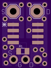
After kicking some ideas around a simple breakout board was designed to cover both low-medium and high current use cases. A handful will be coming from OSH Park within the next couple weeks. Here are top and bottom views of the board:

PowerFetSOIC8-1-topPowerFetSOIC8-1-bottom

Assuming it has no CAD or fabrication bugs, this board will handle any SOIC8 FET with the pins 1-3 for Source, 4, for gate, and 5-8 for drain. The resistor R1 connects the gate to the source to avoid accidental triggering from high Z or open circuit situations.  A value of one megohm should be sufficient. The pads are for an 0805 size resistor. The bottom three pads are for standard or right angle male header pins to go into a standard breadboard. The upper pads are sized for 16 gauge wire to allow high current connections to the source and drain.

Some assembled and bare boards will be brought to the July 13 TriEmbed meeting at NCSU. If the first version is defective we’ll use them to play tiddlywinks. As soon as the board is shown to have no defects the design will be published to the OSH Park “Shared Project” area on their web site.


June 8th Meeting: Lessons learned in an Embedded Systems Course

(Note room change to building 3 (extending through August). Details and maps)

The June  talk will be about what Craig Cook learned between January and May 2015 working on a MOOC (Massive Online Open Course) – “Embedded Systems – Shape the world” provided via edX by lecturers from the University of Austin, Texas, Jonathan Valvano and Ramesh Yerraballi.

Craig Cook has been working in IT since the mid 90’s. Most of his career has been working as a Systems Administrator where computers have plenty of Memory and CPU power and they run an operating system.
Recently Craig became interested in small computers like the Raspberry Pi and Arduino. He wanted to learn more about them. After reading a post to Triembed about an upcoming edX course on embedded systems he decided it was time to jump in.

Triangle Embedded Interest Group