Category Archives: Tools

PCB Board Cleaning: Pure Isopropyl vs MG Cleaner

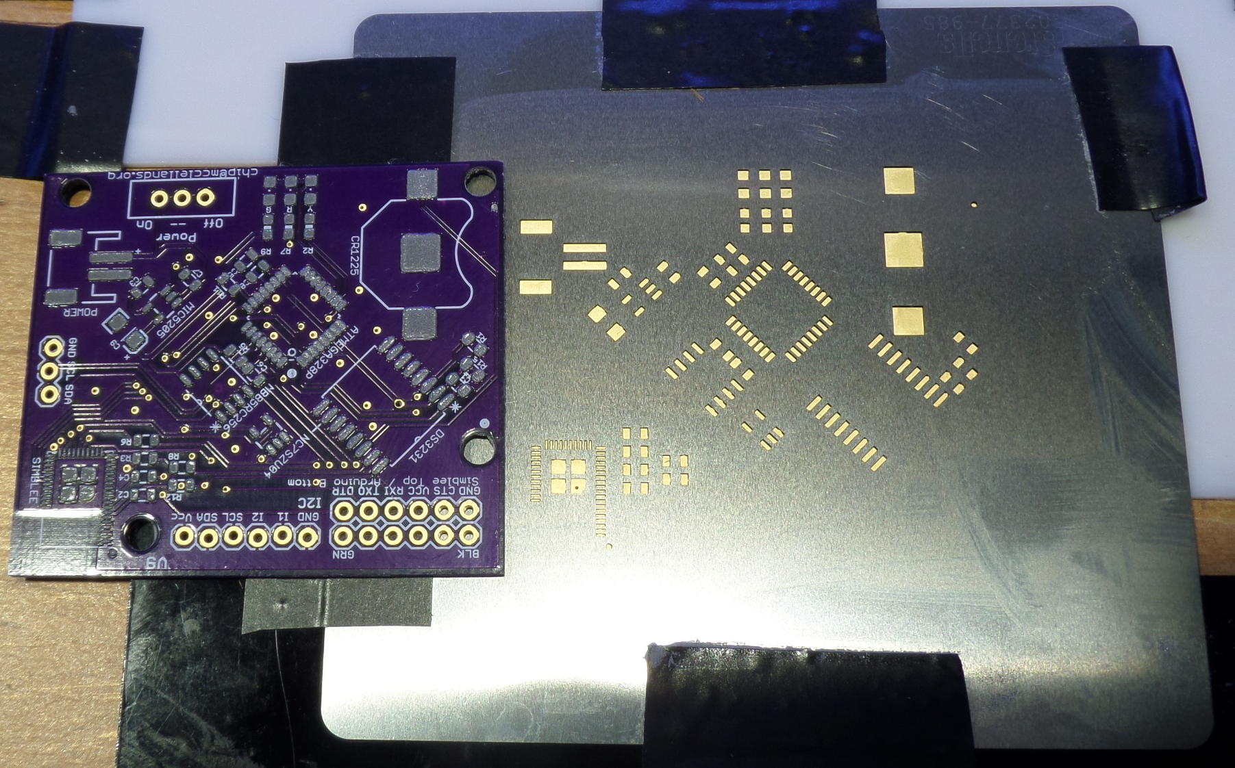
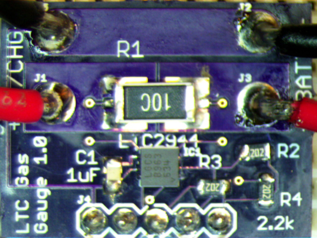
Here’s a breakout board that got a lot of hand soldering with three different kinds of flux. Plain 91{13079d06258ef9010cea88dee32f3cdfc6f216a54651010f7303ce6140ee927c} isopropyl was used after rework using AIM 280 “no clean”  (the watery stuff), which, if used copiously, definitely needs cleaning if you care about appearance. In this case, even scrubbing with a nice (Adafruit) ESD-safe brush would not remove the flux completely as can be seen with this first picture below. The gray cast that’s most pronounced in the lower right corner shows this “can’t clean” flux layer:

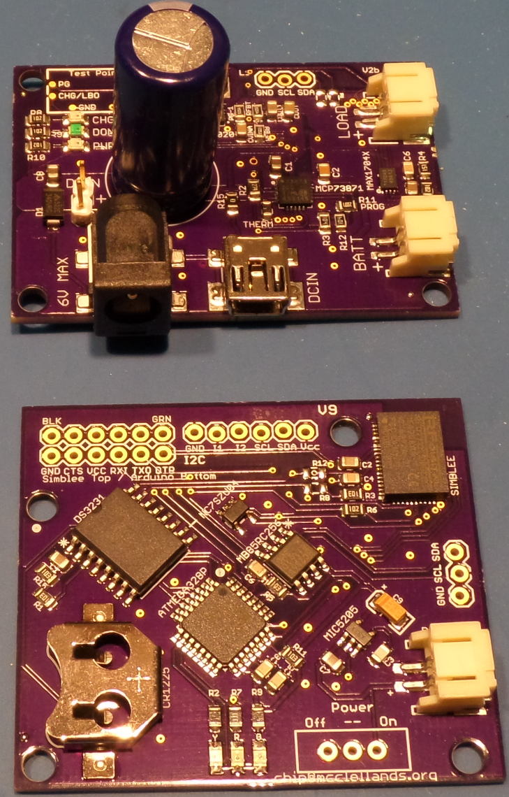
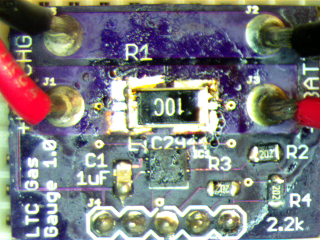
Several rework episodes later, the board had seen lots of the NC flux, but also Chipquik SMD 291 “Tack Flux N/C”, which, in my experience, is never “no clean” except perhaps in the sense of “the electrical connections won’t eventually short out with this stuff”.  From an aesthetic perspective the layer of goo left behind in many cases is simply not nice. Finally, I got lazy with a brute force desoldering method involving braid and old style rosin flux and that stuff is of course just plain nasty. So here’s the very sad “before” photo after the shunt resistor and other parts had been messed with a few times:

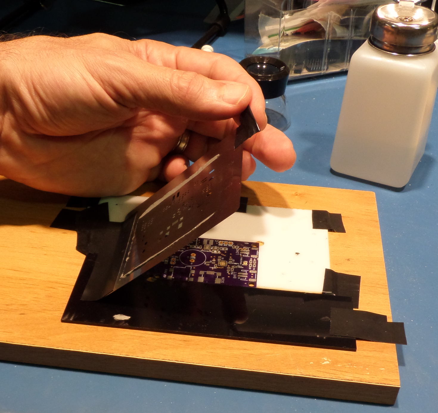
For this case a bit of MG Flux Remover was put into the bottom of a jar, the board was put below the surface, and the jar was swished around for a while. Some exceptionally bad looking, black “baked rosin flux” bits were scrubbed off and then the board got another few seconds in the jar. Then the flux remover was washed off with pure  isopropyl to get the “gunk in solution” level down to zero. (This cheap squirt bottle from Rite Aid works very well for this). Then after the board had dried it looked like this:

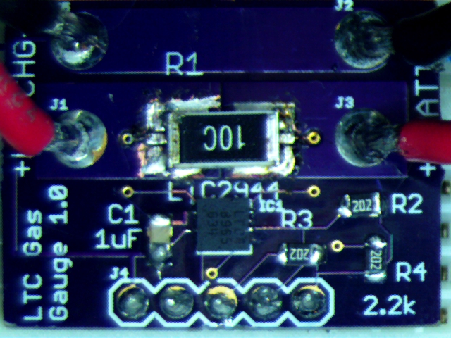
The result was superb: no gray splodges or any other stains. Notice the very tired traces missing solder mask in places. This is what comes of too vigorous scrubbing. The flux remover looks unchanged and I’m expecting that in the tightly sealed jar it has a lot of use left.

I was expecting the remover to have evil stuff in it and was surprised to find it’s  ethanol, isopropyl alcolhol, and ethyl acetate. The latter is found in small quantities in wine (and many homebrew beers). But despite the familiar chemicals I use lots of ventilation for this kind of task.

Thanks to Shane Trent for letting me “try out his jug”.


Notes about OSH Stencils

A few notes from listening to Brent of OSH Stencils: on The Amp Hour:

  • Planning to offer 1.6mm jigs to eliminate the error vis a visa common PCB thickness (hurray)
  • For those that didn’t know:
    • Offering high quality Kester solder paste (in checkout cart, as with the jigs)
    • Offering stainless steel as well as kapton (stainless steel are common 4mil thickness).
  • 5x5mil smallest feature size possible with kapton stencils. Minimum feature size for steel stencils is ONE MIL!
  • They see 70/30{13079d06258ef9010cea88dee32f3cdfc6f216a54651010f7303ce6140ee927c} split between 3mil and 5mil thickness of kapton. The 3mil is best for ordinary work, while the 5mil is appropriate for high power devices with large thermal pads, etc. where a lot of solder is needed. I can vouch for the fact that 5mil is a total disaster for fine pitch parts like a QFN package. Kapton in 4mil is unobtanium, which is why they don’t offer that thickness.
  • Name is OSH Stencils because Brent was originally going to collaborate with Laen of OSH Park, but a change in Laen’s circumstances caused them to remain separate entities and Laen was totally OK with the similarity of names.
  • Can reduce kapton stencil curl by “counter-rolling” the material and this will give temporary relief.
  • Started with hobby laser: That “exploded” the first week after starting business. Switched to Epilog 24 (roughly $30k)
  • Stainless steel stencils made with approx $300k LPKF fiber-based “flagship model” laser cutter
  • Have maintained 24 hour turn time from the beginning. They went with high end laser to be able to make *the best* stainless steel stencils. They are competitive by avoiding framed stencils and using a proprietary material loading system into the LPKF. Basic cost of framed stencil material is 5X the cost of raw. Could use “pneumatic frame” to simulate real frame, but that didn’t allow sheet sizes that were large enough to be cost effective.
  • Brent said their charter as they began making steel stencils was to offer the top quality at reasonable prices. He invited people to compare their metal stencils to Chinese stencils under a microscope as they consider potential “cost savings” by going off shore. (OSH Stencils is in the Salt Lake City area of Utah). The metal makeup is different. Most offshore vendors use “inexpensive stainless steel”. Looking at the apertures (the cutouts) you often see grooves to do with the kerf (diameter of laser beam). With low quality metals the edges of apertures have grooves making them look like washboards.  Also see minor warping and ripples in the Chinese metal.
  • Look for “exciting announcements” to do with the stencil process to be offered by OSH Stencils in coming months.
  • OSH Stencils makes stencils for customers that have nothing to do with electronics. Art projects, special “plates” for mechanical components, etc. They’re open to queries about whether your creative application can be handled by their equipment.

Latest Reflow Progress


SAMSUNG CAMERA PICTURES
Solar Power Management/Charger rev 2B, Trail Counter rev 9
Stainless Steel Stencil from OSH Stencils

Here are Chip McClelland’s latest Trail Counter and Solar Charger boards, together with a shot of the stainless steel stencil now offered by OSH Stencils. The metal stencil makes it hugely easier to get perfect pasting and confirms that the curve that comes with  polymide stencils has been at least one root cause of that type being so challenging to use.  There was no paste bleed through to the back of the stencil, and the fine pitched power controller and Simblee BLE chip lands were perfectly formed. To get a sense of the cost difference some existing board specs were plugged into the OSH Stencils web site: a roughly five square inch battery charger, a three square inch decade counter/divider, and sub-square inch 6-axis breakout board. The steel stencils would be almost exactly double the cost of polymide, averaging about $12 each. By the way,  multiple PCB designs can be grouped within one stencil. This can greatly reduce the cost difference depending on the areas involved.

These are OSH Park boards: very deep blue/purple, sitting on a sky blue antistatic mat. This is a tradeoff with the very bright, high color temperature LED flood lights used to illuminate the bench.

For January 11th: Arduino <==> Raspberry Pi Communication

Paul MacDougal will talk about arranging communication between these two popular single board computers,  and Alex Davis will have a Raspbery Pi with Retropie and MAME to show. This will be followed by the usual show and tell and chat session. Bring your projects, ideas and questions.

We’ll be meeting in EBI room 1007, next door to the one for previous months (and the same as the one TAR is meeting in). This room will be stable through April.

Details and maps here.

Also, we took advantage of TI’s special offer of MSP432 Launchpads. They’ll be available at the meeting for $5. (They will also be at the Splatspace open meeting tomorrow evening.)

MSP432-Launchpad


For the August 10th Meeting: Electronics Tutorials & A Bench Test Instrument

This month’s meeting will be at  NCSU Centennial Campus Engineering Building III:    Meeting Details

The August meeting will be in three parts:

  • Ohm’s Law Modeled With Fluid Flow by Ryan Schuster
  • Transistor Tips by Shane Trent
  • A Programmable Bench Test Instrument Oriented Toward Power Measurements by Chip McClelland

The last part of the meeting will be the usual open forum. Bring your show and tell items, problems needing help, etc.


Battery Testing Resources

LoanerDummyLoad

This is a constant current dummy load made from one of  Shane Trent’s  PCBs like those given away at a recent TriEmbed meeting. As mentioned on the  email list,  this PCB is a “fixed” version of a design from a “Sleepy Robot” blog of a guy named Wittenberg, which is itself a derivation of an original design by Dave Jones of EEVblog.  Wittenberg had made available  gerbers for his design (in early 2012)  that were unfortunately defective, and he didn’t allow for two way communication, forcing Shane to go to great lengths to correct the gerbers and get a run of PCBs fabricated. Shane’s blog article covers all this in depth and has a link to the corrected gerber files in zip format.

Fast forwarding to the present, here’s a recent tutorial by Dave going into depth about battery measurements.  Viewers will just have to put up with the axe-grinding, horse-beating treatment of a “battery life extender” Kickstarter that pushed Dave’s buttons. Apart from this, it’s an excellent treatment and a fantastic “essential subset” spreadsheet tutorial for folks that just want a hint about how to do cool things like the graph-making done in this video.

I assembled and tested a second of the PCBs recently.  It will sink up to one amp at up to around the 60 volt limit of the FET used (MTP3055VL) HOWEVER, unless you like to see magic smoke the 18 watt thermal limit of the FET/heatsink assembly has to be honored. So at a full ampere the voltage limit is around 18, and at that load be sure to avoid touching the transistor! At one ampere the shunt resistor will  be operating at it’s rated dissipation limit and will also be very hot. To summarize, this load has to be kept at an amp or less and at 18 watts of power dissipation or less. (Note: the shunt resistor is temporarily 5{13079d06258ef9010cea88dee32f3cdfc6f216a54651010f7303ce6140ee927c} tolerance due to an ordering blunder. That will be fixed.)

I’ve decided to make it available for borrowing by TriEmbed meeting attendees who can guarantee it’s return by them or their designee at the following month’s meeting. The transistor is not expensive and it won’t be any big disaster (just embarrassing)  if it’s accidentally destroyed, but blowing the traces off the PCB will be frowned upon (joke). So this (and perhaps some of the TriEmbed contact cards Paul made, hallway signs, etc) could be part of a shared resource that could expand over time.

The “UI” is currently two voltmeter test points, with the unit showing the load current as a one to one mapping from amperes to volts. A digital display with simple USB serial (current and “external voltage” aka battery voltage)  logging output and some temperature compensation/auto-calibration is planned, but it would be straight forward to tie the test points  to something like an Arduino analog pin or two.

Remotely controlling and/or making  the current limit programmable would be a bit harder, but a properly coordinated hack to provide an alternative control mechanism would be OK with me and make for a fun project for somebody.

Here are all the design-related links in one place:

Here are some BOM changes:

  • The load connection is just four bare plated through holes intended to get some wire loops. These Newark  12H8386  screw terminals solder in and work well.
  • As mentioned, a momentarily loose screw resulted in this Mouser part 660-MF1/4DCT52R10R0F  five watt resistor being substituted for the default 10 1/4 watt resistors. The bad news is this resistor has a 350ppm/C coefficient as well as being only 5{13079d06258ef9010cea88dee32f3cdfc6f216a54651010f7303ce6140ee927c} tolerance.  A better choice than either might be a pair of three watt, two ohm 1{13079d06258ef9010cea88dee32f3cdfc6f216a54651010f7303ce6140ee927c} Vishay resistors such as Mouser 71-RS02B2R000FE12. These have 50ppm/C coefficient so there would be about another 1/2{13079d06258ef9010cea88dee32f3cdfc6f216a54651010f7303ce6140ee927c} error at the point you could boil water on them.